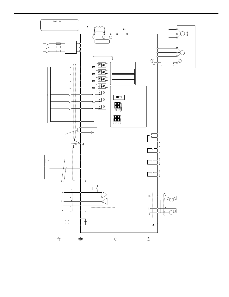
I.4 standard connection diagram – Yaskawa 600V User Manual
Page 17
+
-
+
+
for connection options. Never
connect power supply lines to
these terminals
DC link choke
(option)
U
X
+
-
+
+
+
-
U
X
S
1
S
2
S
3
S
4
S
5
S
6
S
7
A
1
A
2
0 V
AC
R
R
S
S-
IG
Z1000 Drive (600 V)
B
1
1
B
2
2 k
SC
0 V
FM
AM
AC
E (G)
<1>
<2>
<9>
<7>
<8>
<6>
<4>
<3>
-
+
24 V
+
V
M
1
M
2
Jumper
Braking resistor
(option)
Forward Run / Stop
Reverse Run / Stop
External fault
Fault reset
Multi-speed step 1
Multi-speed step 2
Jog speed
Multi-function
digtial inputs
(default setting)
Sink / Source mode
selection
Factory installed wire link
(default: Sink)
CN5-C
CN5-B
CN5-A
Option board
Shield ground terminal
Multi-function
analog inputs
Power supply +10.5 Vdc, max. 20 mA
Analog Input 1 (Frequency Reference Bias)
0 to +10 Vdc (20 kΩ) Resolution: Unsigned 12 bit
4 to 20 mA (250 Ω) / 0 to 20 mA (250 Ω)
MEMOBUS/Modbus Communication
RS-422/RS-485 Maximum 115.2 kbps
BACnet Communication
Apogee FLN, Siemens
Metasys N2, Johnson Controls
Termination resistor
(120 , 1/2 W)
DIP
Switch S2
Multi-function relay output (During Run)
250 Vac, max. 1 A
30 Vdc, max 1 A
(min. 5 Vdc, 10 mA)
Multi-function analog output 1
(Output frequency)
-10 to +10 or 0 to +10 Vdc (2 mA)
or 4 to 20 mA
Main Circuit
Control Circuit
shielded line
twisted-pair shielded line
main circuit terminal
control circuit terminal
R/L1
S/L2
T/L3
R
S
T
Main
Switch
Fuse
EMC
Filter
M
3
M
4
Multi-function relay output (Zero Speed)
250 Vac, max. 1 A
30 Vdc, max 1 A
(min. 5 Vdc, 10 mA)
SP
SN
AM
FM
V
I
Off
On
DIP Switch S2
Term. Res. On/Off
Jumper S1
A1/A2 Voltage/Current
Selection
Jumper S5
AM/FM Voltage/Current
Selection
Terminal board
jumpers and switches
FM
<5>
<10>
Ω
<9>
Multi-function analog output 2
(Output current)
-10 to +10 or 0 to +10 Vdc (2 mA)
or 4 to 20 mA
Three-Phase
Power Supply
600 V
50/60 Hz
<11>
M
U/T
1
V/T
2
W/T
U
FU
FV
FW
V
W
3
Ground
Cooling fan
M
connectors
Ω
Analog Input 2 (Frequency Reference Bias)
0 to +10 Vdc (20 kΩ) Resolution: Unsigned 12 bit
4 to 20 mA (250 Ω) / 0 to 20 mA (250 Ω)
Fault output
250 Vac, max. 1 A
30 Vdc, max 1 A
(min. 5 Vdc, 10 mA)
MA
MB
MC
V
I
A1 A2
FE
M
5
M
6
Multi-function relay output (Speed Agree 1)
250 Vac, max. 1 A
30 Vdc, max 1 A
(min. 5 Vdc, 10 mA)
External power supply
24 Vdc, max. 150 ma
Terminals , 1, 2, B1, B2 are
+
-
AM
++
2
+P
SN
+24 Vdc
External
Supply
(max. 150 mA)
-
+
Figure i.5 Drive Standard Connection Diagram
<1> Remove the jumper when installing a DC link choke. Models 5A0041 to 5A0242 come with a built-in DC link choke.
<2> Set L8-55 to 0 to disable the protection function of the built-in braking transistor of the drive when using an optional regenerative
converter or dynamic braking option. Leaving L8-55 enabled may cause a braking resistor fault (rF). Additionally, disable Stall
Prevention (L3-04 = 0) when using an optional regenerative converter, regenerative or braking units, or dynamic braking option.
Leaving If L3-04 enabled may prevent the drive from stopping within the specified deceleration time.
<3> Supplying power to the control circuit separately from the main circuit requires 24 V power supply (option).
i.4 Standard Connection Diagram
YASKAWA ELECTRIC TOEP YAIZ1U 02A YASKAWA AC Drive – Z1000 Safety Precautions
17