Terminal fm/am signal selection, Memobus/modbus termination, Table i.12 – Yaskawa 600V User Manual
Page 31: I.4 standard connection diagram
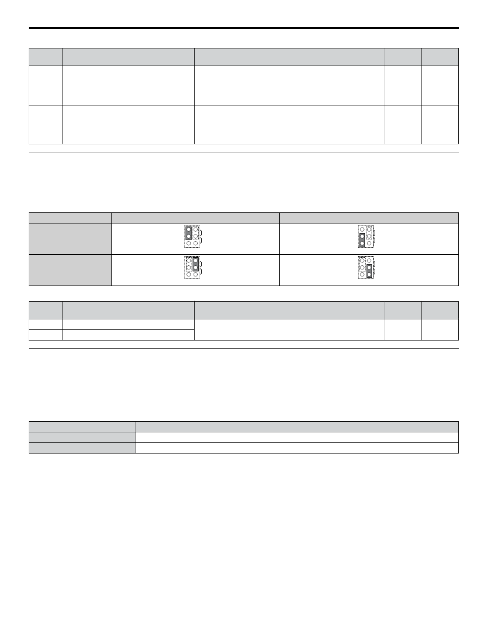
Table i.12 Parameters H3-01 and H3-09 Details
No.
Parameter Name
Description
Setting
Range
Default
Setting
H3-01
Terminal A1 signal level selection
Selects the signal level for terminal A1.
0: 0 to 10 V with Zero Limit
1: 0 to 10 V without Zero Limit
2: 4 to 20 mA Current Input
3: 0 to 20 mA Current Input
0 to 3
0
H3-09
Terminal A2 signal level selection
Selects the signal level for terminal A2.
0: 0 to 10 V with Zero Limit
1: 0 to 10 V without Zero Limit
2: 4 to 20 mA Current Input
3: 0 to 20 mA Current Input
0 to 3
0
u
Terminal FM/AM Signal Selection
The signal type for terminals FM and AM can be set to either voltage or current output using jumper S5 on the terminal board
as explained in
. When changing the setting of jumper S5, parameters H4-07 and H4-08 must be set accordingly.
The default selection is voltage output for both terminals.
Table i.13 Jumper S5 Settings
Terminal
Voltage Output
Current Output
Terminal FM
AM
FM
V
I
AM
FM
V
I
Terminal AM
AM
FM
V
I
AM
FM
V
I
Table i.14 Parameter H4-07 and H4-08 Details
No.
Parameter Name
Description
Setting
Range
Default
Setting
H4-07
Terminal FM signal level selection
0: 0 to 10 Vdc
2: 4 to 20 mA
0, 2
0
H4-08
Terminal AM signal level selection
u
MEMOBUS/Modbus Termination
This drive is equipped with a built-in termination resistor for the RS-422/485 communication port. DIP switch S2 enables or
disabled the termination resistor as shown in
. The OFF position is the default. The termination resistor should be
placed to the ON position when the drive is the last in a series of slave drives.
Refer to Switches and Jumpers on the Terminal
Table i.15 MEMOBUS/Modbus Switch Settings
S2 Position
Description
ON
Internal termination resistor ON
OFF
Internal termination resistor OFF (default setting)
i.4 Standard Connection Diagram
YASKAWA ELECTRIC TOEP YAIZ1U 02A YASKAWA AC Drive – Z1000 Safety Precautions
31