Terminal configuration, Control circuit input terminals – Yaskawa 600V User Manual
Page 25
u
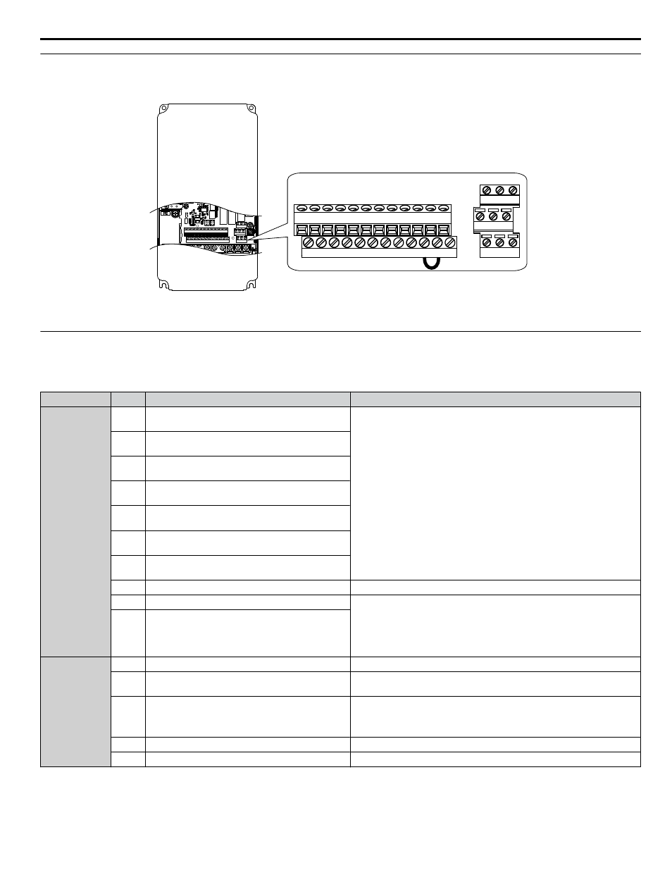
Terminal Configuration
The control circuit terminals are arranged as shown in
IG R+ R- S+ S- +V AC A1 A2 FM AM AC
FE S1 S2 S3 S4 S5 S6 S7 SN SC SP +P
M3 M4 M6
M1 M2 M5
MA MB MC
IG R+ R- S+ S- +V AC A1 A2 FM AM AC
FE S1 S2 S3 S4 S5 S6 S7 SN SC SP +P
M3 M4 M6
M1 M2 M5
MA MB MC
Figure i.7 Control Circuit Terminal Arrangement
u
Control Circuit Input Terminals
lists the input terminals on the drive. Text in parenthesis indicates the default setting for each multi-function input.
Table i.6 Control Circuit Input Terminals
Type
No.
Terminal Name (Function)
Function (Signal Level) Default Setting
Multi-Function
Digital Inputs
S1
Multi-function input 1
(Closed: Forward run, Open: Stop)
• Photocoupler
• 24 Vdc, 8 mA
•
Refer to Sinking/Sourcing Mode for Digital Inputs on page 30
.
S2
Multi-function input 2
(Closed: Reverse run, Open: Stop)
S3
Multi-function input 3
(External fault, N.O.)
S4
Multi-function input 4
(Fault reset)
S5
Multi-function input 5
(Multi-step speed reference 1)
S6
Multi-function input 6
(Multi-step speed reference 2)
S7
Multi-function input 7
(Jog reference)
SC
Multi-function input common
Multi-function input common
SP
Digital input power supply +24 Vdc
24 Vdc power supply for digital inputs, 150 mA max (only when not using
digital input option DI-A3)
NOTICE: Do not jumper or short terminals SP and SN. Failure to
comply will damage the drive.
SN
Digital input power supply 0 V
Analog Inputs /
Pulse Train
Input
+V
Power supply for analog inputs
10.5 Vdc (max allowable current 20 mA)
A1
Multi-function analog input 1
(Frequency reference bias)
-10 to 10 Vdc, 0 to 10 Vdc (input impedance: 20 kΩ)
A2
Multi-function analog input 2
(Frequency reference bias)
• -10 to 10 Vdc, 0 to 10 Vdc (input impedance: 20 kΩ)
• 4 to 20 mA, 0 to 20 mA (input impedance: 250 Ω)
• Voltage or current input must be selected by DIP switch S1 and H3-09.
AC
Frequency reference common
0 V
FE
Ground for shielded lines and option cards
–
i.4 Standard Connection Diagram
YASKAWA ELECTRIC TOEP YAIZ1U 02A YASKAWA AC Drive – Z1000 Safety Precautions
25