Protecting main circuit terminals, Main circuit wire gauges and tightening torque – Yaskawa 600V User Manual
Page 19
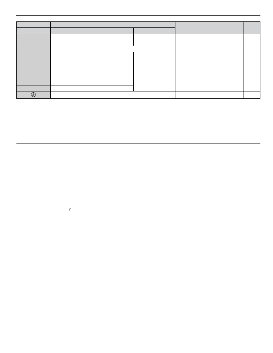
Terminal
Type
Function
Page
Drive Model
5A0003 to 5A0032
5A0041, 5A0052
5A0062 to 5A0242
B1
Braking resistor
Not available
Available for connecting a braking
resistor or a braking resistor unit option
–
B2
⊕2
• DC link choke
connection
(
⊕1, ⊕2)
(remove the shorting
bar between
⊕1 and ⊕2)
• DC power supply
input
(
⊕1, ⊖)
Not available
For connecting:
• the drive to a DC power supply
• dynamic braking options
• a DC link choke
–
⊕1
DC power supply input
(
⊕1, ⊖)
• DC power supply
input (
⊕1, ⊖)
• Braking unit
connection (
⊕3, ⊖)
⊖
⊕3
Not available
10 Ω or less
Grounding terminal
Note:
Use terminals B1 and
⊖ when installing a CDBR-type braking unit on drives with built-in braking transistors (Models 5A0003 to 5A0052).
u
Protecting Main Circuit Terminals
n
Insulation Caps or Sleeves
Use insulation caps or sleeves when wiring the drive with crimp terminals. Take particular care to ensure that the wiring does
not touch nearby terminals or the surrounding case.
u
Main Circuit Wire Gauges and Tightening Torque
Use the tables in this section to select the appropriate wires and crimp terminals.
Gauges listed in the tables are for use in the United States.
Note:
1. Wire gauge recommendations based on drive continuous current ratings (ND) using 75 °C 600 Vac vinyl-sheathed wire assuming ambient
temperature within 40 °C and wiring distance less than 100 m.
2. Terminals
⊕1, ⊕2, ⊕3, ⊖, B1 and B2 are for connecting optional power devices. Use caution to connect only approved devices to the
correct terminal(s).
• Consider the amount of voltage drop when selecting wire gauges. Increase the wire gauge when the voltage drop is greater
than 2% of motor rated voltage. Ensure the wire gauge is suitable for the terminal block. Use the following formula to
calculate the amount of voltage drop:
Line drop voltage (V) = 3 × wire resistance (Ω/km) × wire length (m) × current (A) × 10
-3
• Refer to instruction manual TOBP C720600 00 for braking transistor option or braking resistor option wire gauges.
• Use terminals
⊕1 and ⊖ when connecting a regenerative converter or a regen unit.
NOTICE: Do not connect a braking resistor to terminals
⊕1 or ⊖. Failure to comply may cause damage to the drive circuitry.
• Use terminals B1 and
⊖ when installing a CDBR-type braking unit on drives with built-in braking transistors (models
5A0003 to 5A0052).
NOTICE: Do not connect a braking resistor to terminals
⊕1 or ⊖. Failure to comply may cause damage to the drive circuitry.
•
Refer to UL Standards Compliance on page 53
for information on UL compliance.
Yaskawa recommends using closed-loop crimp terminals on all drive models. Use only the tools recommended by the terminal
manufacturer for crimping.
Refer to Closed-Loop Crimp Terminal Size on page 23
for closed-loop crimp terminal
recommendations.
The wire gauges listed below are Yaskawa recommendations. Refer to local codes for proper wire gauge selections.
i.4 Standard Connection Diagram
YASKAWA ELECTRIC TOEP YAIZ1U 02A YASKAWA AC Drive – Z1000 Safety Precautions
19