I.7 parameter table – Yaskawa 600V User Manual
Page 40
No.
Name
Description
b5-44
Custom PI Output
Monitor Setting 2
Sets the minimum display value at zero
speed.
b5-07 and b5-08 show Custom PI output.
This function is effective when b5-42 is set
to 1 (Linear unit)
b5-45
Custom PI Output
Monitor Setting 3
b5-46
PI Setpoint Monitor
Unit Selection
0: WC (Inch of water)
1: PSI (Pounds per square inch)
2: GPM (Gallons per minute)
3: F (Degrees Fahrenheit)
4: CFM (Cubic feet per minute)
5: CMH (Cubic meters per hour)
6: LPH (Liters per hour)
7: LPS (Liters per second)
8: Bar (Bar)
9: Pa (Pascal)
10: C (Degrees Celsius)
11: Mtr (Meters)
12: Ft (Feet)
13: LPM (Liters per minute)
14: CMM (Cubic meters per minute)
b5-47
Reverse Operation
Selection 2 by PI
Output
Reverse operation selection when b5-01 =
3
0: Reverse Disabled
1: Reverse Enabled
b8-01
Energy Saving Control
Selection
0: Disabled
1: Enabled
Note: Default setting is dependent upon
parameter A1-02, Control Method
Selection.
C1-01
Acceleration Time 1
Sets the time to accelerate from 0 to
maximum frequency.
C1-02
Deceleration Time 1
Sets the time to decelerate from maximum
frequency to 0.
C1-11
Accel/Decel Time
Switching Frequency
Sets the frequency to switch between accel/
decel time settings
C2-01
S-Curve Characteristic
at Accel Start
S-curve at acceleration start.
C2-02
S-Curve Characteristic
at Accel End
S-curve at acceleration end.
C6-02
Carrier Frequency
Selection
1: 2.0 kHz
2: 5.0 kHz
3: 8.0 kHz
4: 10.0 kHz
5: 12.5 kHz
6: 15.0 kHz
7: Swing PWM1 (Audible sound 1)
8: Swing PWM2 (Audible sound 2)
9: Swing PWM3 (Audible sound 3)
A: Swing PWM4 (Audible sound 4)
B to E: No setting possible
F: User-defined (determined by C6-03
through C6-05)
Note: Default setting value is dependent
upon parameters A1-02, Control Method
Selection and o2-04, Drive Model Selection
C6-03
Carrier Frequency
Upper Limit
Determines the upper and lower limits for
the carrier frequency.
Carrier Frequency
E1-04
Max Output
Frequency
Output Frequency
× (C6-05) × K
Output
Frequency
C6-03
C6-04
C6-04
Carrier Frequency
Lower Limit
C6-05
Carrier Frequency
Proportional Gain
d1-01 to
d1-16
Frequency Reference 1
to 4; 16
Sets the frequency reference for the drive.
Setting units are determined by parameter
o1-03.
d1-17
Jog Frequency
Reference
Sets the Jog frequency reference. Setting
units are determined by parameter o1-03.
No.
Name
Description
d2-01
Frequency Reference
Upper Limit
Sets the frequency reference upper limit as
a percentage of the maximum output
frequency.
d2-02
Frequency Reference
Lower Limit
Sets the frequency reference lower limit as
a percentage of the maximum output
frequency.
d2-03
Master Speed
Reference Lower Limit
Sets the lower limit for frequency
references from analog inputs as a
percentage of the maximum output
frequency.
E1-01
Input Voltage Setting
This parameter must be set to the power
supply voltage.
E1-03
V/f Pattern Selection
0: 50 Hz, Constant torque 1
1: 60 Hz, Constant torque 2
2: 60 Hz, Constant torque 3 (50 Hz base)
3: 72 Hz, Constant torque 4 (60 Hz base)
4: 50 Hz, Variable torque 1
5: 50 Hz, Variable torque 2
6: 60 Hz, Variable torque 3
7: 60 Hz, Variable torque 4
8: 50 Hz, High starting torque 1
9: 50 Hz, High starting torque 2
A: 60 Hz, High starting torque 3
B: 60 Hz, High starting torque 4
C: 90 Hz (60 Hz base)
D: 120 Hz (60 Hz base)
E: 180 Hz (60 Hz base)
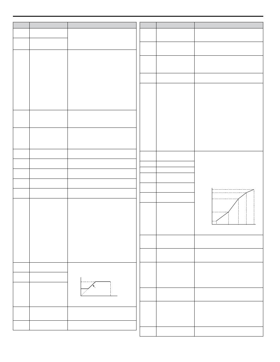
F: Custom V/f E1-04 through E1-13
settings define the V/f pattern
E1-04
Maximum Output
Frequency
These parameters are only applicable when
E1-03 is set to F.
To set linear V/f characteristics, set the
same values for E1-07 and E1-09.
In this case, the setting for E1-08 will be
disregarded. Ensure that the four
frequencies are set according to these rules:
E1-09 ≤ E1-07 < E1-06 ≤ E1-11 ≤ E1-04
Output Voltage (V)
Frequency (Hz)
E1-05
E1-12
E1-13
E1-08
E1-10
E1-09
E1-07 E1-06 E1-11 E1-04
E1-05
Maximum Voltage
E1-06
Base Frequency
E1-07
Middle Output
Frequency
E1-08
Middle Output
Frequency Voltage
E1-09
Minimum Output
Frequency
E1-10
Minimum Output
Frequency Voltage
E2-01
Motor Rated Current
Sets the motor nameplate full load current
in amps. Automatically set during
Auto-Tuning.
E2-11
Motor Rated Power
Sets the motor rated power in kilowatts
(1 HP = 0.746 kW). Automatically set
during Auto-Tuning.
F6-01
Communications Error
Operation Selection
0: Ramp to stop. Decelerate to stop using
the deceleration time in C1-02.
1: Coast to stop
2: Fast Stop. Decelerate to stop using the
deceleration time in C1-09.
3: Alarm only
H1-01 to
H1-07
Multi-Function Digital
Input Terminal S1 to
S7 Function Selection
Selects the function of terminals S1 to S7.
H3-01
Terminal A1 Signal
Level Selection
0: 0 to 10 V with zero limit
1: 0 to 10 V without zero limit
2: 4-20 mA
3: 0-20 mA
Note: Use Jumper S1 to set input terminal
A1 for a current or voltage input signal.
H3-02
Terminal A1 Function
Selection
Sets the function of terminal A1.
i.7 Parameter Table
40
YASKAWA ELECTRIC TOEP YAIZ1U 02A YASKAWA AC Drive – Z1000 Safety Precautions