I.7 parameter table – Yaskawa 600V User Manual
Page 39
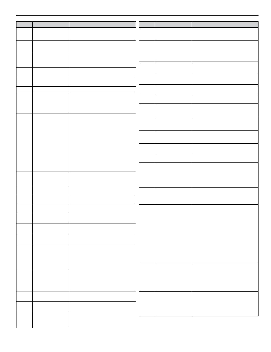
No.
Name
Description
b5-04
Integral Limit Setting
Sets the maximum output possible from the
integrator as a percentage of the maximum
output frequency.
b5-06
PI Output Limit
Sets the maximum output possible from the
entire PI controller as a percentage of the
maximum output frequency.
b5-07
PI Offset Adjustment
Applies an offset to the PI controller output.
Set as a percentage of the maximum output
frequency.
b5-08
PI Primary Delay Time
Constant
Sets a low pass filter time constant on the
output of the PI controller.
b5-09
PI Output Level
Selection
0: Normal output (direct acting)
1: Reverse output (reverse acting)
b5-10
PI Output Gain Setting Sets the gain applied to the PI output.
b5-11
PI Output Reverse
Selection
0: Negative PI output triggers zero limit.
1: Rotation direction reverses with negative
PI output.
Note: When using setting 1, make sure
reverse operation is permitted by b1-04.
b5-12
PI Feedback Loss
Detection Selection
0: Digital Output Only
(Remains active when PI is disabled by
digital input)
1: Alarm output, drive continues operation
(Remains active when PI is disabled by
digital input)
2: Fault output, drive output is shut off
(Remains active when PI is disabled by
digital input)
3: Digital output only. No detection when
PI is disabled by digital input.
4: Alarm detection. No detection when PI is
disabled by digital input.
5: Fault detection. No detection when PI is
disabled by digital input.
b5-13
PI Feedback Loss
Detection Level
Sets the PI feedback loss detection level as
a percentage of the maximum output
frequency.
b5-14
PI Feedback Loss
Detection Time
Sets a delay time for PI feedback loss.
b5-15
PI Sleep Function Start
Level
Sets the frequency level that triggers the
sleep/snooze function.
b5-16
PI Sleep Delay Time
Sets a delay time before the sleep/snooze
function is triggered.
b5-17
PI Accel/Decel Time
Sets the acceleration and deceleration time
to PI setpoint.
b5-18
PI Setpoint Selection
0: Disabled
1: Enabled
b5-19
PI Setpoint Value
Sets the PI target value when b5-18 = 1. Set
as a percentage of the maximum output
frequency.
b5-20
PI Setpoint Scaling
0: 0.01 Hz units
1: 0.01% units (100% = max output
frequency)
2: r/min (number of motor poles must
entered)
3: User-set (set scaling to b5-38 and b5-39)
b5-21
PI Sleep Input Source
Input source selection for Sleep Function
mode.
0: PI Setpoint
1: SFS Input
2: Snooze
b5-22
PI Snooze Level
Sets the PI Snooze Function start level as a
percentage of the maximum frequency.
b5-23
PI Snooze Delay Time Sets the PI Snooze Function delay time in
seconds.
b5-24
PI Snooze
Deactivation Level
When the PI feedback level drops below
this level, the drive returns to normal
operation. Set as a percentage of the
maximum frequency.
No.
Name
Description
b5-25
PI Setpoint Boost
Setting
Temporarily increases the PI setpoint to
create an overshoot of the intended PI
setpoint.
b5-26
PI Maximum Boost
Time
Sets the maximum boost time when PI
feedback does not reach boost level.
The Snooze Function starts when the PI
feedback exceeds the boost setting level or
when the boost time expires.
b5-27
PI Snooze Feedback
Level
Sets the PI feedback level above which
Snooze mode is activated. Set as a
percentage of the maximum frequency.
b5-28
PI Feedback Function
Selection
0: Disabled
1: Square root
b5-29
PI Square Root Gain
A multiplier applied to the square root of the
feedback.
b5-30
PI Feedback Offset
PI feedback offset set as a percentage of the
maximum frequency.
b5-34
PI Output Lower Limit
Sets the minimum output possible from the
PI controller as a percentage of the
maximum output frequency.
b5-35
PI Input Limit
Limits the PI control input (deviation
signal) as a percentage of the maximum
output frequency. Acts as a bipolar limit.
b5-36
PI Feedback High
Detection Level
Sets the PI feedback high detection level as
a percentage of the maximum output
frequency.
b5-37
PI Feedback High
Detection Time
Sets the PI feedback high level detection
delay time.
b5-38
PI Setpoint User
Display
Sets the display value of U5-01 and U5-04
when the maximum frequency is output.
b5-39
PI Setpoint Display
Digits
0: No decimal places
1: One decimal place
2: Two decimal places
3: Three decimal places
Note: Default setting is dependent upon
parameter b5-20, PI Setpoint Scaling.
b5-40
Frequency Reference
Monitor Content
during PI
0: Display the frequency reference (U1-01)
after PI compensation has been added.
1: Display the frequency reference (U1-01)
before PI compensation has been added.
b5-41
PI Unit Selection
0: WC (Inch of water)
1: PSI (Pounds per square inch)
2: GPM (Gallons per minute)
3: F (Degrees Fahrenheit)
4: CFM (Cubic feet per minute)
5: CMH (Cubic meters per hour)
6: LPH (Liters per hour)
7: LPS (Liters per second)
8: Bar (Bar)
9: Pa (Pascal)
10: C (Degrees Celsius)
11: Mtr (Meters)
12: Ft (Feet)
13: LPM (Liters per minute)
14: CMM (Cubic meters per minute)
b5-42
PI Output Monitor
Calculation Method
0: Linear - the monitor displays PI
output
1: Square root - the monitor displays square
root PI output
2: Quadratic - the monitor displays 1/(PI
output)
3: Cubic - the monitor displays 1/(PI output)
b5-43
Custom PI Output
Monitor Setting 1
Set maximum monitor value at maximum
frequency.
U5-07 and U5-08 show Custom PI output.
U5-43 shows the upper four digits and
U5-44 shows the lower four digits.
It shows 999999.99 maximum.
i.7 Parameter Table
YASKAWA ELECTRIC TOEP YAIZ1U 02A YASKAWA AC Drive – Z1000 Safety Precautions
39