Refer to, Figure i.11, Connect control wires as shown in – Yaskawa 600V User Manual
Page 28: Figure i.9, Figure i.10, I.4 standard connection diagram
A
B
C
D
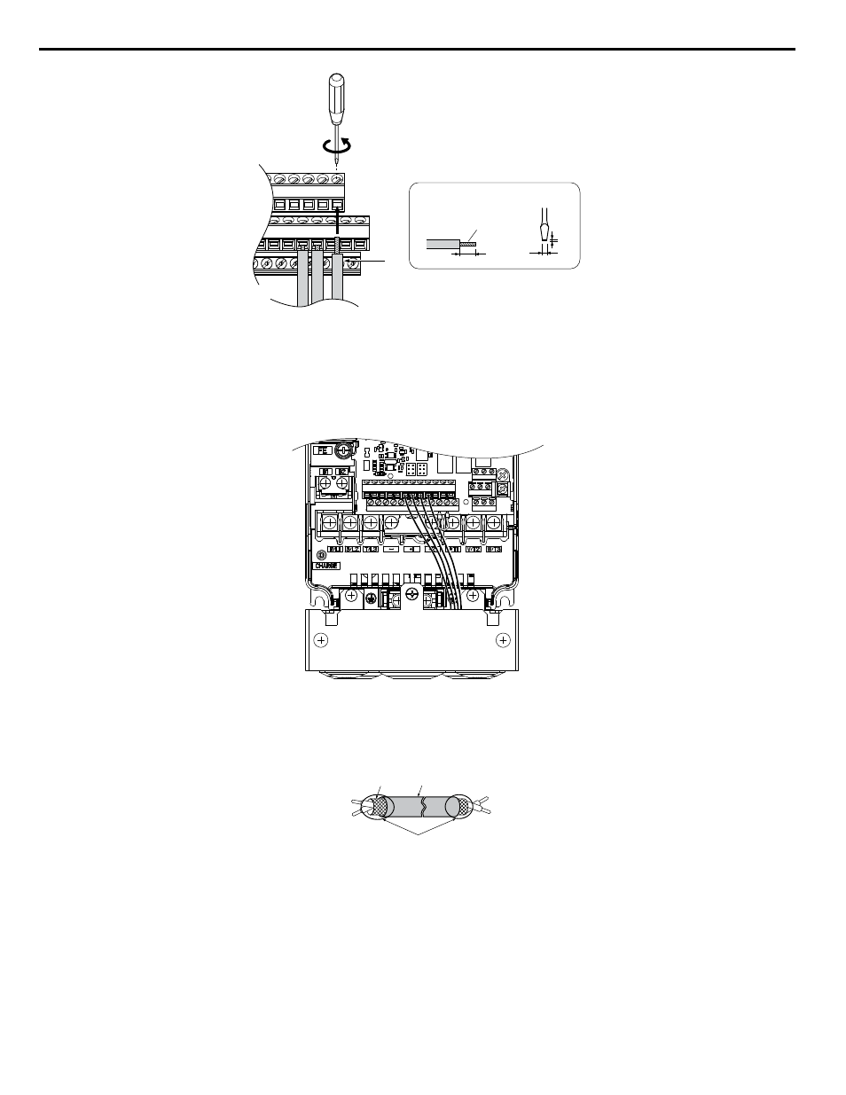
Preparing wire
terminal ends
A – Loosen screw to insert wire.
B – Single wire or stranded wire
C – Avoid fraying wire strands when
stripping insulation from wire. Strip
length 5.5 mm.
D – Blade depth of 0.4 mm or less
Blade width of 2.5 mm or less
Figure i.9 Terminal Board Wiring Guide
Figure i.10 Terminal Board Location Inside the Drive
When setting the frequency by analog reference from an external potentiometer, use shielded twisted-pair wires (preparing
wire ends as shown in
) and connect the shield to the ground terminal of the drive.
A
E
B
C
D
A – Drive side
B – Insulation
C – Control device side
D – Shield sheath (insulate with tape)
E – Shield
Figure i.11 Preparing the Ends of Shielded Cables
NOTICE: The analog signal wiring between the drive and the operator station or peripheral equipment should not exceed 50 meters when
using an analog signal from a remote source to supply the frequency reference. Failure to comply could result in poor system performance.
i.4 Standard Connection Diagram
28
YASKAWA ELECTRIC TOEP YAIZ1U 02A YASKAWA AC Drive – Z1000 Safety Precautions