I.7 parameter table – Yaskawa 600V User Manual
Page 42
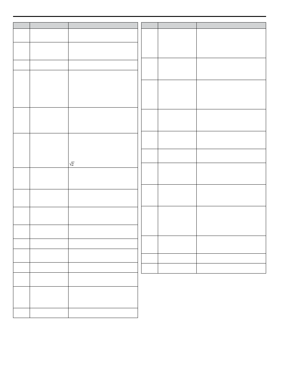
No.
Name
Description
L6-14
Motor Underload
Protection Level at
Minimum Frequency
Sets the UL6 detection level at minimum
frequency by percentage of drive rated
current.
L8-01
Internal Dynamic
Braking Resistor
Protection Selection
(ERF type)
0: Resistor overheat protection disabled
1: Resistor overheat protection enabled
L8-02
Overheat Alarm Level An overheat alarm occurs when heatsink
temperature exceeds the L8-02 level.
L8-03
Overheat Pre-Alarm
Operation Selection
0: Ramp to stop. A fault is triggered.
1: Coast to stop. A fault is triggered.
2: Fast Stop. Decelerate to stop using the
deceleration time in C1-09. A fault is
triggered.
3: Continue operation. An alarm is
triggered.
4: Continue operation at reduced speed
as set in L8-19.
L8-05
Input Phase Loss
Protection Selection
Selects the detection of input current phase
loss, power supply voltage imbalance, or
main circuit electrolytic capacitor
deterioration.
0: Disabled
1: Enabled
L8-06
Input Phase Detection
Level
When ripple is observed in the DC bus,
expansion of the input bias is calculated.
This value becomes the input phase if the
difference between the maximum and
minimum values of the ripple is greater than
the value set to L8-06.
Detection Level = 100% = Voltage class x
L8-07
Output Phase Loss
Protection Selection
0: Disabled
1: Enabled (triggered by a single phase
loss)
2: Enabled (triggered when two phases are
lost)
L8-09
Output Ground Fault
Detection Selection
0: Disabled
1: Enabled
Note: Default setting is dependent upon
parameter o2-04, Drive Model Selection.
L8-10
Heatsink Cooling Fan
Operation Selection
0: During run only. Fan operates only
during run for L8-11 seconds after stop.
1: Fan always on. Cooling fan operates
whenever the drive is powered up.
L8-11
Heatsink Cooling Fan
Off Delay Time
Sets a delay time to shut off the cooling fan
after the Run command is removed when
L8-10 = 0.
L8-12
Ambient Temperature
Setting
Enter the ambient temperature. This value
adjusts the oL2 detection level.
L8-15
oL2 Characteristics
Selection at Low
Speeds
0: No oL2 level reduction below 6 Hz.
1: oL2 level is reduced linearly below 6
Hz. It is halved at 0 Hz.
L8-18
Software Current Limit
Selection
0: Disabled
1: Enabled
L8-19
Frequency Reduction
Rate during Overheat
Pre-Alarm
Specifies the frequency reference reduction
gain at overheat pre-alarm when L8-03 = 4.
L8-27
Overcurrent Detection
Gain
Sets the gain for overcurrent detection as a
percentage of the motor rated current.
Overcurrent is detected using the lower
value between the overcurrent level of the
drive or the value set to L8-27.
L8-29
Current Unbalance
Detection (LF2)
0: Disabled
1: Enabled
No.
Name
Description
L8-32
Main Contactor and
Cooling Fan Power
Supply Failure
Selection
0: Ramp to stop
1: Coast to stop
2: Fast stop (Decelerate to stop using the
deceleration time set to C1-09)
3: Alarm only (“FAn” will flash)
4: Continue operation at reduced speed as
set to L8-19.
L8-35
Installation Method
Selection
0: IP00/Open-Chassis enclosure
2: IP20/NEMA Type 1 enclosure
3: External Heatsink Installation
Note: Default setting is dependent upon
parameter o2-04, Drive Model Selection.
L8-38
Carrier Frequency
Reduction
0: Disabled
1: Enabled below 6 Hz
2: Enabled for the entire speed range
Note: Default setting is dependent upon
parameters A1-02, Control Method
Selection, and o2-04, Drive Model
Selection.
L8-40
Carrier Frequency
Reduction Off Delay
Time
Sets the time that the drive continues
running with reduced carrier frequency
after the carrier reduction condition is gone.
Setting 0.00 s disables the carrier frequency
reduction time.
L8-41
High Current Alarm
Selection
0: Disabled
1: Enabled.
An alarm is triggered at output currents
above 150% of drive rated current.
L8-55
Internal Braking
Transistor Protection
0: Disabled. Disable when using a regen
converter or optional braking unit.
1: Protection enabled.
o1-01
Drive Mode Unit
Monitor Selection
Selects the content of the last monitor that
is shown when scrolling through Drive
Mode display. Enter the last three digits of
the monitor parameter number to be
displayed: Uo-oo.
o1-02
User Monitor Selection
after Power Up
1: Frequency reference (U1-01)
2: Direction
3: Output frequency (U1-02)
4: Output current (U1-03)
5: User Monitor
o1-03
HOA Keypad Operator
Display Selection
0: 0.01 Hz
1: 0.01% (100% = E1-04)
2: r/min (calculated using the number of
motor poles setting in E2-04, E4-04, or
E5-04)
3: User-selected units (set by o1-10 and
o1-11)
o1-06
User Monitor Selection
Mode
0: 3 Monitor Sequential
(Displays the next two sequential monitors)
1: 3 Monitor Selectable (o1-07 and o1-08
selected monitor are shown)
o1-70
Second Line Monitor
Selection
Selects the monitor that is shown in the
second line.
o1-08
Third Line Monitor
Selection
Selects the monitor that is shown in the third
line.
i.7 Parameter Table
42
YASKAWA ELECTRIC TOEP YAIZ1U 02A YASKAWA AC Drive – Z1000 Safety Precautions