For closed-loop crimp terminal, I.4 standard connection diagram – Yaskawa 600V User Manual
Page 23
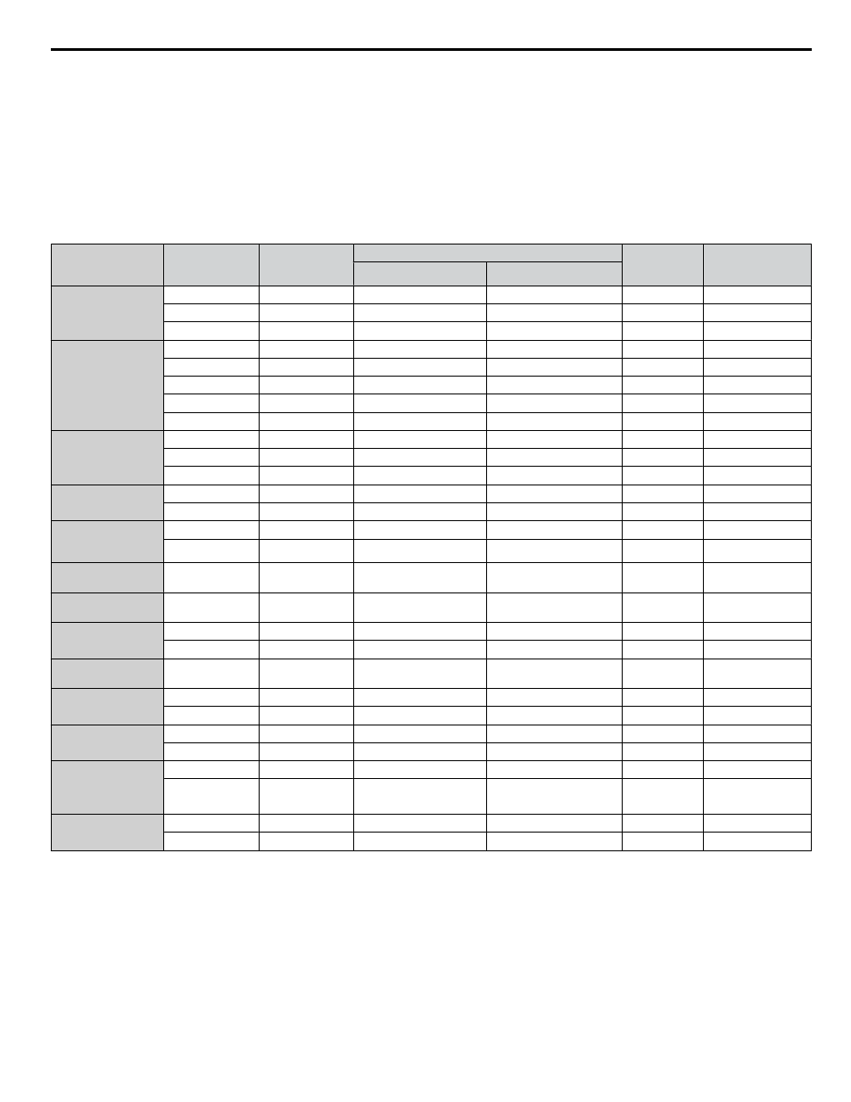
Closed-Loop Crimp Terminal Recommendations
To maintain UL/cUL approval, UL Listed closed-loop crimp terminals are specifically required when wiring the drive main
circuit terminals on models 5A0041 to 5A0242. Use only the tools recommended by the terminal manufacturer for crimping.
Yaskawa recommends UL listed crimp terminals made by JST and Tokyo DIP (or equivalent) for the insulation cap.
matches the wire gauges and terminal screw sizes with Yaskawa-recommended crimp terminals, tools, and insulation caps.
Refer to the appropriate Wire Gauge and Torque Specifications table for the wire gauge and screw size for your drive model.
Place orders with a Yaskawa representative or the Yaskawa sales department.
The closed-loop crimp terminal sizes and values listed in
are Yaskawa recommendations. Refer to local codes for
proper selections.
Table i.5 Closed-Loop Crimp Terminal Size
Wire Gauge
Terminal
Screws
Crimp Terminal
Model Number
Tool
Insulation
Cap
Model No.
Code
<1>
Machine No.
Die Jaw
8 AWG
M4
8-4
YA-4
AD-901
TP-008
100-054-031
M5
R8-5
YA-4
AD-901
TP-008
100-054-032
M8
R8-8
YA-4
AD-901
TP-008
100-061-111
6 AWG
M4
14-NK4
YA-4
AD-902
TP-014
100-054-033
M5
R14-5
YA-4
AD-902
TP-014
100-054-034
M6
R14-6
YA-5
AD-952
TP-014
100-051-261
M8
R14-8
YA-5
AD-952
TP-014
100-054-035
M10
R14-10
YA-5
AD-952
TP-014
100-061-112
4 AWG
M6
R22-6
YA-5
AD-953
TP-022
100-051-262
M8
R22-8
YA-5
AD-953
TP-022
100-051-263
M10
R22-10
YA-5
AD-953
TP-022
100-061-113
3 / 2 AWG
M8
R38-8
YA-5
AD-954
TP-038
100-051-264
M10
R38-10
YA-5
AD-954
TP-038
100-061-114
1 AWG
1/0 AWG
1/0 AWG × 2P
M8
R60-8
YA-5
AD-955
TP-060
100-051-265
M10
R60-10
YF-1, YET-300-1
TD-321, TD-311
TP-060
100-051-266
1 AWG × 2P
2 AWG × 2P
M10
38-L10
YF-1, YET-150-1
TD-224, TD-212
TP-038
100-051-556
2/0 / 3/0 AWG
2/0 AWG × 2P
M10
80-10
YF-1, YET-300-1
TD-323, TD-312
TP-080
100-051-267
3/0 AWG × 2P
3/0 AWG × 4P
M10
80-L10
YF-1, YET-150-1
TD-227, TD-214
TP-080
100-051-557
M12
80-L12
YF-1, YET-300-1
TD-323, TD-312
TP-080
100-051-558
4/0 AWG
M10
R100-10
YF-1, YET-300-1
YF-1, YET-150-1
TD-324, TD-312
TD-228, TD-214
TP-100
100-051-269
4/0 AWG × 2P
4/0 AWG × 4P
M10
100-L10
YF-1, YET-150-1
TD-228, TD-214
TP-100
100-051-559
M12
100-L12
YF-1, YET-300-1
TD-324, TD-312
TP-100
100-051-560
250 / 300 kcmil
M10
R150-10
YF-1. YET-150-1
TD-229, TD-215
TP-150
100-051-272
M12
R150-12
YF-1, YET-300-1
TD-325, TD-313
TP-150
100-051-273
250 kcmil × 2P
250 kcmil × 4P
300 kcmil × 2P
300 kcmil × 4P
M10
150-L10
YF-1, YET-150-1
TD-229, TD-215
TP-150
100-051-561
M12
150-L12
YF-1, YET-300-1
TD-325, TD-313
TP-150
100-051-562
350 kcmil
400 kcmil
M10
200-10
YF-1, YET-300-1
TD-327, TD-314
TP-200
100-051-563
M12
R200-12
YF-1, YET-300-1
TD-327, TD-314
TP-200
100-051-275
<1> Codes refer to a set of three crimp terminals and three insulation caps. Prepare input and output wiring using two sets for each connection.
Example 1: Models with 300 kcmil for both input and output require one set for input terminals and one set for output terminals, so the user should
order two sets of [100-051-272].
Example 2: Models with 4/0 AWG × 2P for both input and output require two sets for input terminals and two sets for output terminals, so the user
should order four sets of [100-051-560].
Note:
Use crimp insulated terminals or insulated shrink tubing for wiring connections. Wires should have a continuous maximum allowable
temperature of 75 °C 600 Vac UL-approved vinyl-sheathed insulation.
i.4 Standard Connection Diagram
YASKAWA ELECTRIC TOEP YAIZ1U 02A YASKAWA AC Drive – Z1000 Safety Precautions
23