11 appendix 3 terminal size and wire gauge – Yaskawa GPD515/G5 User Manual
Page 74
11 Appendix 3 Terminal Size and Wire Gauge
74
YASKAWA PL.A1000.01 G5 to A1000 - Product Transition Guide
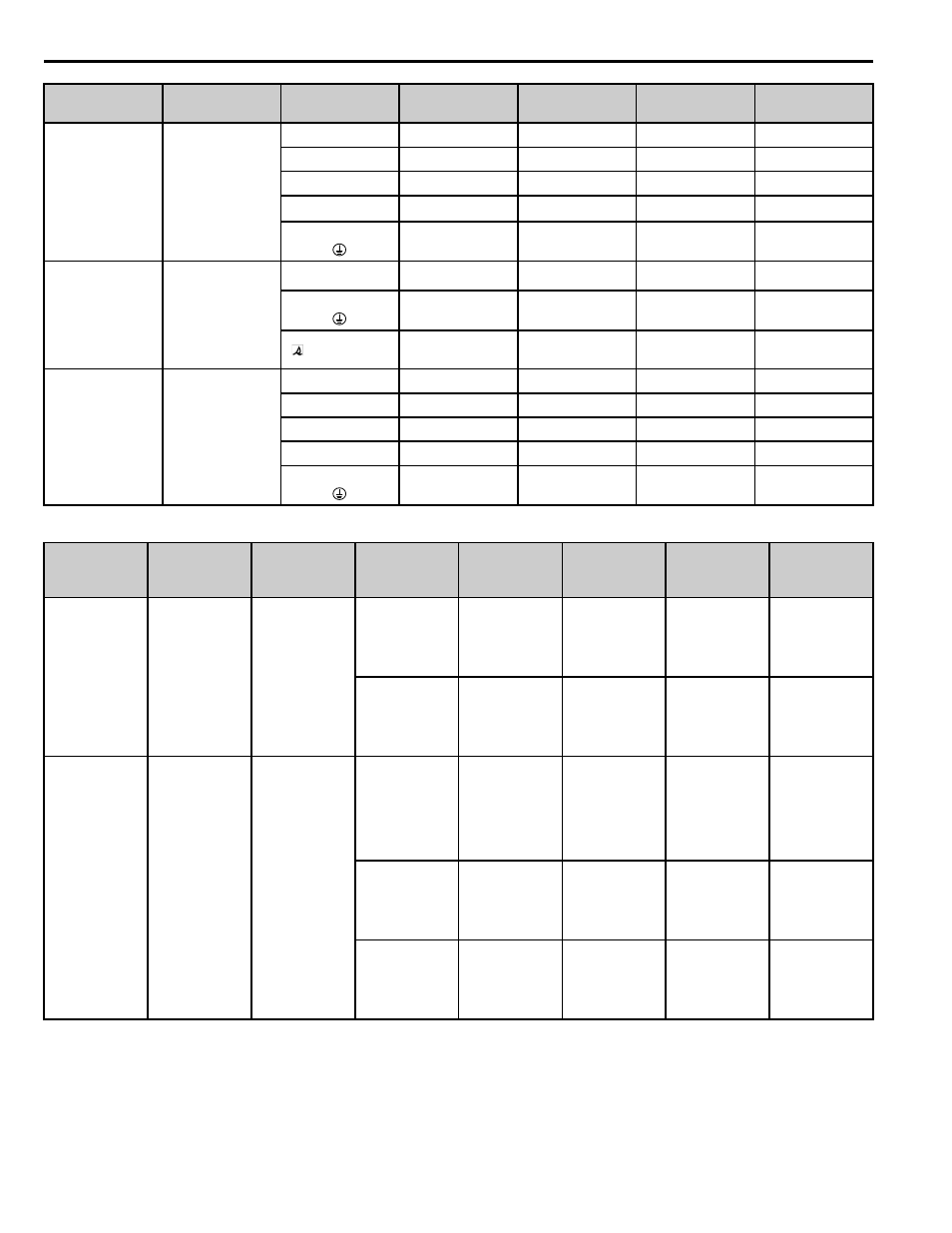
Table 28 Control Circuit Terminal Size and Wire Gauge
A1000
5A0192
R/L1, S/L2, T/L3
─
─
─
─
U/T1, V/T2, W/T3
─
─
─
─
-, +1, +2
─
─
─
─
B1, B2
─
─
─
─
─
─
─
─
G5
5160
R/L1, S/L2, T/L3,
U/T1, V/T2, W/T3, -, +3
M4
─
180 to 200
(350 to 400)
─
Pressure
Lug
─
30 to 60
(3 to 2/0)
─
r,
M4
─
2 to 5.5
(14 to 10)
─
A1000
5A0242
R/L1, S/L2, T/L3
─
─
─
─
U/T1, V/T2, W/T3
─
─
─
─
-, +1, +2
─
─
─
─
B1, B2
─
─
─
─
─
─
─
─
Power Supply
Series
Capacity
Terminal Signal
Terminal Screw
Tightening Torque
(N ・ m)
Wire Range
AWG
(mm
2
)
Recommended
Gauge
AWG
(mm
2
)
200 V Class
400 V Class
G5
All capacities
1 to 11, 13 to 33
M3.5
─
Stranded wire:
0.5 to 1.25
Single Line
0.5 to 1.25
─
12 (G)
M3.5
─
0.5 to 2.0
─
200 V Class
400 V Class
A1000
All capacities
FM, AC, AM, P1,
P2, PC,
SC, SN, SP, A1, A2,
A3, +V, -V,
S1, S2, S3, S4, S5,
S6,S7, S8,
MA, MB, MC, M1-
M6
Phoenix type
4.2 to 5.3
(0.5 to 0.6)
Stranded wire:
26 to 16
(0.14 to 1.5)
18
(0.75)
MP, RP, R+, R-, S+,
S-, IG
DM+, DM-, H1, H2,
HC
Phoenix type
4.2 to 5.3
(0.5 to 0.6)
Stranded wire:
26 to 16
(0.14 to 1.5)
18
(0.75)
E (G)
M3.5
7.0 to 8.8
(0.8 to 1.0)
20 to 14
(0.5 to 2.0)
12
(1.25)
Series
Model
Terminal Signal
Terminal
Screw
Tightening Torque
N ・ m (lb.in.)
Possible Gauges
mm
2
(AWG/kcmil)
Recommended
Gauge mm
2
(AWG/
kcmil)