Terminal board set-up comparison, 6 main control pcb comparison, Table 6 factory default functions 2-wire control – Yaskawa GPD515/G5 User Manual
Page 11
6 Main Control PCB Comparison
YASKAWA PL.A1000.01 G5 to A1000 - Product Transition Guide
11
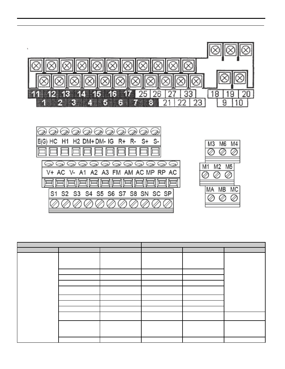
Terminal Board Set-Up Comparison
Figure 1
Figure 1 GPD515/G5 Terminal Board Configuration
Figure 2
Figure 2 A1000 Terminal Board Configuration
Table 6 Factory Default Functions 2-Wire Control
GPD515/G5 Terminal
A1000 Terminal (Designations similar to GPD515/G5)
Type
GPD515/G5 Terminal
Default Functions
A1000 Terminal
Default Function
A1000 Description
Digital Input Signals
1
Forward run/stop
Signal level:
(Photo-coupler insulated
Input: +24 Vdc, 8 mA)
S1
Forward run/stop command
Multi-function inputs 1-8
Photocoupler
24 Vdc, 8 mA
Set the S3 jumper to select
between sinking, sourcing
mode, and the power supply.
2
Reverse run/stop
S2
Reverse run/stop command
3
External fault input
S3
External fault input
4
Fault reset input
S4
Fault reset
5
Master/Auxilary change
Multi-step speed reference 1
S5
Multi-step speed reference 1
(Master/auxiliary switch)
6
Multi-step speed reference 2
S6
Multi-step speed reference 2
7
Jog reference
S7
Jog frequency reference
8
External baseblock
S8
External baseblock N.O.
11
Sequence control input
common
SN
Digital input common
Multi-function input
common
—
—
SC
Factory connected to SP
24 Vdc Power Supply for
Digital inputs, 150 mA max
(only when not using digital
input option DI-A3)
—
—
SP
Factory connected to SC