10 appendix 2 parameter cross reference – Yaskawa GPD515/G5 User Manual
Page 57
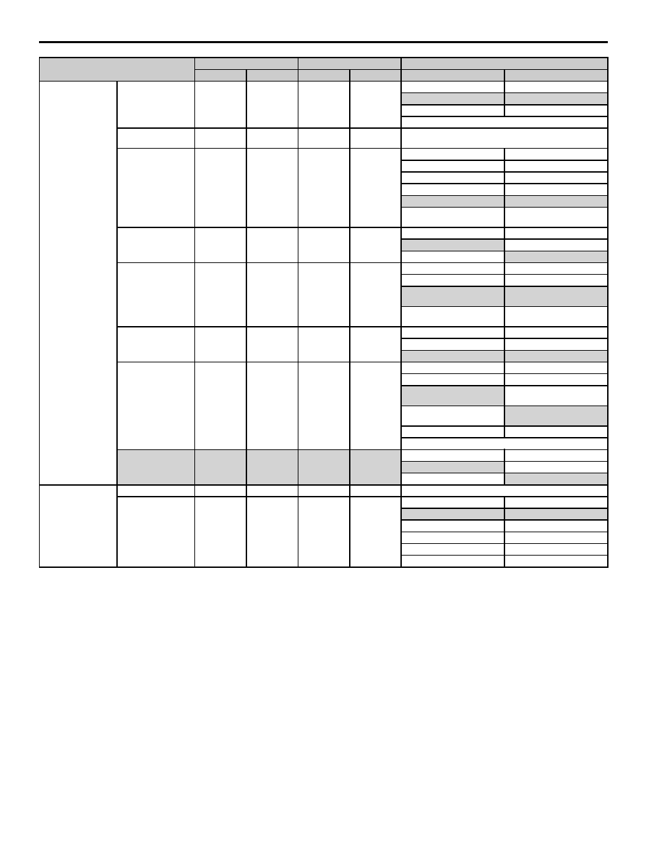
10 Appendix 2 Parameter Cross Reference
YASKAWA PL.A1000.01 G5 to A1000 - Product Transition Guide
57
Hardware Protection
Protect Selection for
Internal DB Resistor
(Type ERF)
L8-01
0
L8-01
0*
L8-01
L8-01
0: Disabled
0: Disabled
1: Enabled
1: Enabled
*Depends on drive capacity
Overheat Pre-Alarm
Level
L8-02
95°C
L8-02
*
*Depends on drive capacity.
Operation Selection
after Overheat Pre-
Alarm
L8-03
3
L8-03
3
L8-03
L8-03
0: Ramp to stop
0: Ramp to stop
1: Coast to stop
1: Coast to stop
2: Fast Stop
2: Fast Stop
3: Alarm Only
3: Alarm Only
─
4: Reduce the frequency and
continue operation
Input Open-Phase
Protection Selection
L8-05
0
L8-05
1
L8-05
L8-05
0: Disabled
0: Disabled
1: Enabled
1: Enabled
Output Open-Phase
Protection Selection
L8-07
1
L8-07
1
L8-07
L8-07
0: Disabled
0: Disabled
1: Enabled
1: Enabled (triggered by a
single phase loss)
─
2: Enabled (triggered when two
phases are lost)
Ground Protection
Selection
L8-10
1
L8-09
1
L8-10
L8-09
0: Disabled
0: Disabled
1: Enabled
1: Enabled
Carrier Frequency
Reduction Selection
L8-17
1
L8-38
2*
L8-17
L8-38
0: No reduction
0: No derating
1: With carrier frequency
reduction
1: Derating when overload
below 6 Hz
2: For factory adjustments
2: Frequency derating with
overload
3: For factory adjustments
*Depends on drive capacity.
oL2 Characteristics
Selection at Low
Speeds
L8-19
0
L8-15
1
L8-19
L8-15
0: Disabled
0: Disabled
1: Enabled
1: Enabled
Display Setting/
Selection
Monitor Selection
o1-01
6*
o1-01
106*
*See the “comments” column for parameter F4-01.
Monitor Selection
After Power Up
o1-02
1
o1-02
1
o1-02
o1-02
1: Frequency reference
1: Frequency reference
2: Output frequency
3: Output frequency
3: Output current
4: Output current
4: Determined by o1-01
5: Determined by o1-01
─
2: RWD/REV
Parameter Name
G5
A1000
Comments (Gray shading indicates default settings)
No.
Default
No.
Default
G5
A1000