10 appendix 2 parameter cross reference – Yaskawa GPD515/G5 User Manual
Page 46
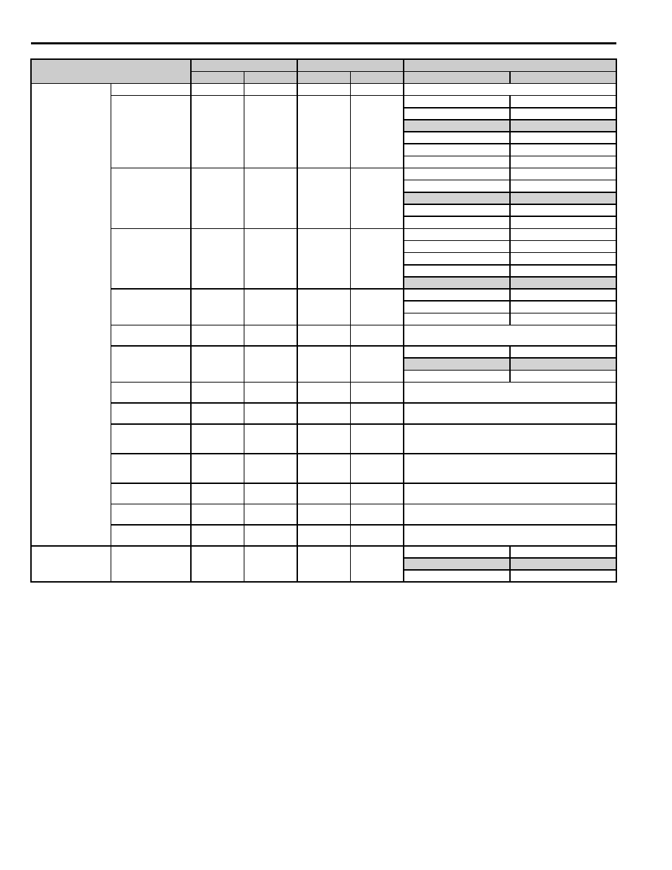
10 Appendix 2 Parameter Cross Reference
46
YASKAWA PL.A1000.01 G5 to A1000 - Product Transition Guide
PG speed Control Card
PG constant
F1-01
1024
F1-01
1024
―
Operation Selection at
PG Open Circuit
(PGO)
F1-02
1
F1-02
1
F1-02
F1-02
0: Ramp to stop
0: Ramp to stop
1: Coast to stop
1: Coast to stop
2: Fast Stop
2: Fast Stop
3: Continue operation
3: Continue operation
―
4: No Alarm Display
Operation Selection at
Overspeed (OS)
F1-03
1
F1-03
1
F1-03
F1-03
0: Ramp to stop
0: Ramp to stop
1: Coast to stop
1: Coast to stop
2: Fast Stop
2: Fast Stop
3: Continue operation
3: Continue operation
Operation Selection at
Deviation
F1-04
3
F1-04
3
F1-04
F1-04
0: Ramp to stop
0: Ramp to stop
1: Coast to stop
1: Coast to stop
2: Fast Stop
2: Fast Stop
3: Continue operation
3: Continue operation
PG Rotation Selection
F1-05
0
F1-05
0
F1-05
F1-05
0: FWD = A pulse leads
0: FWD = A pulse leads
1: FWD = B pulse leads
1: FWD = B pulse leads
PG Division Rate (PG
Pulse Monitor)
F1-06
1
F1-06
1
Enabled when using the PG-B2 option card.
Integral Value During
Accel/Decel Enable/
Disable
F1-07
0
C5-12
0
F1-07
C5-12
0: Disabled
0: Disabled
1: Enabled
1: Enabled
Overspeed Detection
Level
F1-08
115 %
F1-08
115 %
―
Overspeed Detection
Delay Time
F1-09
0.0 s
F1-09
1.0 s
─
Excessive Speed
Deviation Detection
Level
F1-10
10 %
F1-10
10 %
─
Excessive Speed
Deviation Detection
Delay Time
F1-11
0.5 s
F1-11
0.5 s
─
Number of PG Gear
Teeth 1
F1-12
0
F1-12
0
─
Number of PG Gear
Teeth 2
F1-13
0
F1-13
0
─
PG Open-Circuit
Detection Time
F1-14
2.0 s
F1-14
2.0 s
─
Analog Command
Card
Bi-polar or uni-polar
input selection
F2-01
0
F2-01
0
F2-01
F2-01
0: 3CH seperate input functions
0: Separate input functions
1: 3CH inputs added together
1: Sum of inputs for freq ref
Parameter Name
G5
A1000
Comments (Gray shading indicates default settings)
No.
Default
No.
Default
G5
A1000