10 appendix 2 parameter cross reference – Yaskawa GPD515/G5 User Manual
Page 54
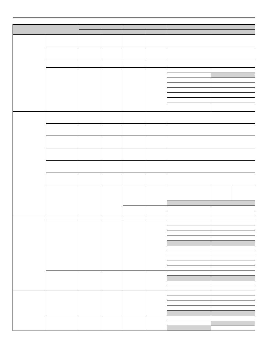
10 Appendix 2 Parameter Cross Reference
54
YASKAWA PL.A1000.01 G5 to A1000 - Product Transition Guide
Analog Input
Gain (terminal 14)
(terminal A2 for
A1000)
H3-10
100.0 %
H3-11
100.0 %
―
Bias (terminal 14)
(terminal A2 for
A1000)
H3-11
0.0 %
H3-12
0.0%
―
Analog Input Filter
Time Constant
H3-12
0.03 s
H3-13
0.03 s
―
Analog Input Terminal
Enable Selection
─
─
H3-14
7
─
H3-14
─
1: Terminal A1 enabled
─
2: Terminal A2 enabled
─
3: Terminals A1, A2 enabled
─
4: Terminal A3 enabled
─
5: Terminals A1, A3 enabled
─
6: Terminals A2, A3 enabled
─
7: Terminals A1, A2, and A3
enabled
Multi-Function Analog
Output
Monitor Selection
(terminal 21) (terminal
FM for A1000)
H4-01
2*
H4-01
102*
*Refer to the “Comments” column for F4-01
Gain (terminal 21)
(terminal FM for
A1000)
H4-02
1.00
H4-02
100.0 %
Setting units differ between G5 and A1000.
Set A1000 by multiplying H4-05 in G5 by 100.
Bias (terminal 21)
(terminal FM for
A1000)
H4-03
0.0 %
H4-03
0.0 %
―
Monitor Selection
(terminal 23) (terminal
FM for A1000)
H4-04
3*
H4-04
103*
*Refer to the “Comments” column for F4-01
Gain (terminal 23)
(terminal FM for
A1000)
H4-05
0.50
H4-05
50.0 %
Setting units differ between G5 and A1000.
Set A1000 by multiplying H4-05 in G5 by 100.
Bias (terminal 23)
(terminal FM for
A1000)
H4-06
0.0 %
H4-06
0.0 %
―
Multi-Function Analog
Output Signal Level
Selection
H4-07
0
H4-07
(FM monitor)
0
H4-07
H4-07
Terminal FM
Signal Level
Selection
H4-08
Terminal AM
Signal Level
Selection
0: 0 to +10 V output
0: 0 to 10 V
H4-08
(AM monitor)
0
1: 0 to ±10 V output
1: -10 to 10 V
―
2: 4 to 20 mA
MEMOBUS
Communication
Station Address
H5-01
1F
H5-01
1F
―
Communication Speed
Selection
H5-02
3
H5-02
3
H5-02
H5-02
0: 1200 bps
0: 1200 bps
1: 2400 bps
1: 2400 bps
2: 4800 bps
2: 4800 bps
3: 9600 bps
3: 9600 bps
4: 19200 bps
4: 19200 bps
─
5: 38400 bps
─
6: 57600 bps
─
7: 76800 bps
─
8: 115200 bps
Communication Parity
Selection
H5-03
0
H5-03
0
H5-03
H5-03
0: No parity
0: No parity
1: Even parity
1: Even parity
2: Odd parity
2: Odd parity
MEMOBUS
Communication
Stopping Method After
Communication Error
H5-04
3
H5-04
0
H5-04
H5-04
0: Ramp to stop
0: Ramp to stop
1: Coast to stop
1: Coast to stop
2: Fast Stop
2: Fast Stop
3: Alarm Only
3: Alarm Only
Communication Error
Detection Selection
H5-05
1
H5-05
0
H5-05
H5-05
0: Disabled
0: Disabled
1: Enabled
1: Enabled
Parameter Name
G5
A1000
Comments (Gray shading indicates default settings)
No.
Default
No.
Default
G5
A1000