10 appendix 2 parameter cross reference – Yaskawa GPD515/G5 User Manual
Page 47
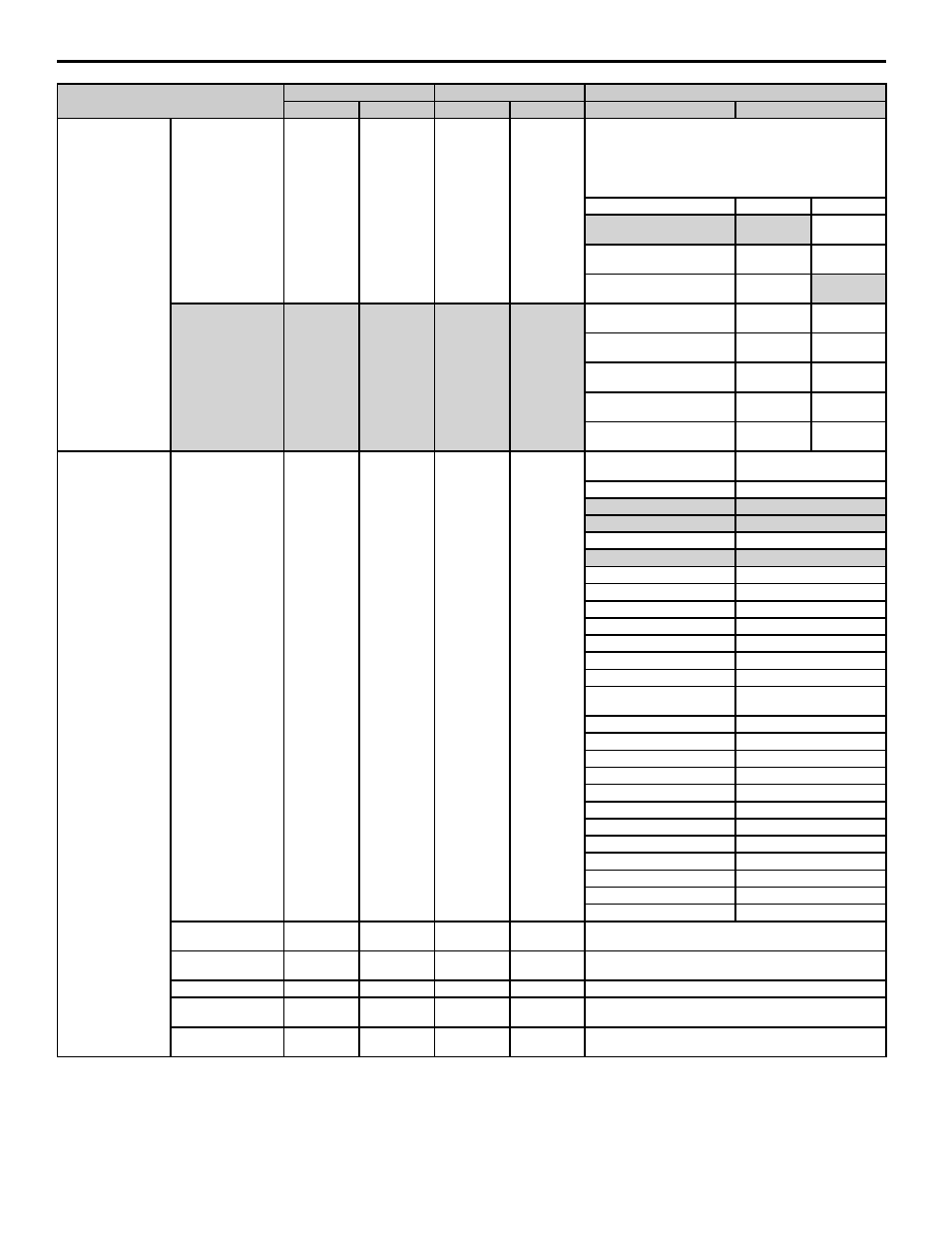
10 Appendix 2 Parameter Cross Reference
YASKAWA PL.A1000.01 G5 to A1000 - Product Transition Guide
47
Digital Command Card
Digital Input Option
F3-01
0
F3-01
0
*The digital option card determines the setting
DI-08: 0 (8 bit)
DI-16H: Set switch S1 to determine input signal:
S1 switch 1: 2 (16 bit)
S1 switch S1: 1 (12 bit)
F3-01
F3-01
F3-03
0: BCD 1 % units
0: BCD 1 %
units
0: 8 bit
1: BCD 0.1 % units
1: BCD 0.1 %
units
1: 12 bit
2: BCD 0.01 % units
2: BCD
0.01 % units
2: 16 bit
Bit Selection for
Digital Card Input Data
─
─
F3-03
2*
3: BCD 1 Hz units
3: BCD 1 Hz
units
─
4: BCD 0.1 Hz units
4: BCD 0.1
Hz units
─
5: BCD 0.01 Hz units
5: BCD 0.01
Hz units
─
6: BCD, custom
6: BCD,
custom
─
7: Binary input
7: Binary
input
─
Analog Monitor Card
Channel 1 Monitor
Selection
F4-01
2
F4-01
102
F4-01, F4-03, H4-01, H4-04,
o1-01
F4-01, F4-03, H4-01, H4-04,
o1-01
01: Frequency reference
101: Frequency reference
02: Output frequency
102: Output frequency
03: Output current
103: Output current
05: Motor speed
105: Motor speed
06: Output voltage reference
106: Output voltage reference
07: Main circuit DC voltage
107: Main circuit DC voltage
08: Output power
108: Output power
09: Torque ref (Internal)
109: Torque ref (Internal)
15: Freq ref, 13 voltage
113: Freq ref, A1 voltage
16: Freq ref, 14 voltage
114: Freq ref, A2 voltage
17: Freq ref, 16 voltage
115: Freq ref, A3 voltage
18: Secondary current (Iq)
601: Secondary current (Iq)
19: Motor excitation current
(Id)
602: Motor excitation current
(Id)
20: Output after soft start
116: Output after soft start
21: ASR input
603: ASR input
22: ASR output
604: ASR output
23: Speed bias
Setting not available in A1000
24: PID feedback amount
501: PID feedback amount
26: Output voltage ref (Vq)
605: Output voltage ref (Vq)
27: Output voltage ref (Vd)
606: Output voltage ref (Vd))
32: ACR output (q-axis)
607: ACR output (q-axis)
33: ACR output (d-axis)
608: ACR output (d-axis)
36: PID input amount
502: PID input amount
37: PID output amount
503: PID output amount
38: PID setpoint
504: PID setpoint
Channel 1 Gain
F4-02
1.00
F4-02
100.0 %
Setting units differ between G5 and A1000. Set A1000 by
multiplying F4-02 in G5 by 100.
Channel 2 Monitor
Selection
F4-03
3*
F4-03
103*
*See the comments column for F4-01.
Channel 2 Gain
F4-04
50.0
F4-04
50.0 %
Set A1000 by multiplying F4-04 in G5 by 100.
Channel 1 output
Monitor Bias
F4-05
0.0 %
F4-05
0.0 %
─
Channel 2 Output
Monitor Bias
F4-06
0.0 %
F4-06
0.0 %
─
Parameter Name
G5
A1000
Comments (Gray shading indicates default settings)
No.
Default
No.
Default
G5
A1000