8 "pfcnst" procedure, Pfcnst" procedure – SMA SC 500HE-US User Manual
Page 43
SMA America, LLC
8 Reactive Power Regulation
Operating Manual
SC500HEUS-eng-BE-BUS120320
43
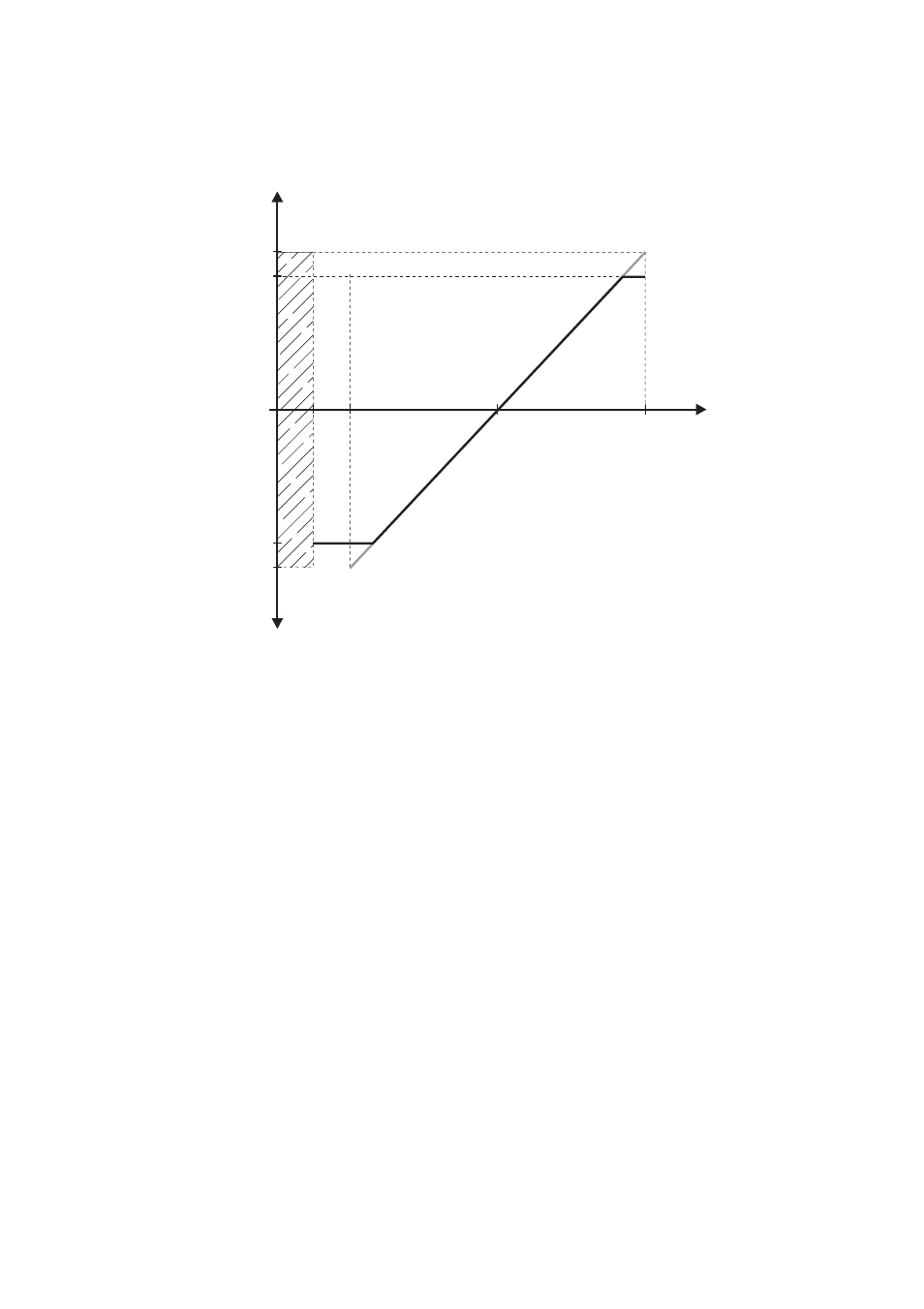
The analog value is converted to a target value for power limitation. Here, the parameter "Pmax" is
the end point of the linear characteristic curve.
Figure 12: Limiting the parameter "Pmax" to the parameter "Qmax"
If the value of "Pmax" exceeds the value of "Qmax", the characteristic curve of the value Q
max
will be
limited to "Qmax" and the reactive power value in the range from +Q
max
to +P
max
will constantly
remain at "Qmax".
If the value of "‒Pmax" falls below the value of "‒Qmax", the characteristic curve of the value ‒Q
max
will be limited to "‒Qmax" and the reactive power value in the range from ‒Q
max
to ‒P
max
will
constantly remain at "‒Qmax".
8.1.8 "PFCnst" Procedure
The reactive power setpoint is set using the parameters "PF-PF" and "PF-PFExt". The parameter "PF-PF"
indicates the displacement power factor cos φ and the parameter "PF-PFExt" indicates the degree of
overexcitation or underexcitation. The parameter "PFAbsMin" is the start and end point of the linear
characteristic curve.
Parameters used
None
Parameters used
PF-PF
PF-PFExt
11,5
Q [VAr]
19
4
2
- Q
max
- P
max
0
I [mA]
Q
max
P
max