HEIDENHAIN PWM 20 User Manual
Page 235
236
HEIDENHAIN ATS Software User's Manual
(CLOCK) is received within this time (t
2
or t
2
+t
R
), the same data will be output once again.
If data output is interrupted (CLOCK = high for t t
2
) a new measured value is saved with the
next falling edge. With the next rising clock edge the subsequent electronics adopts the data.
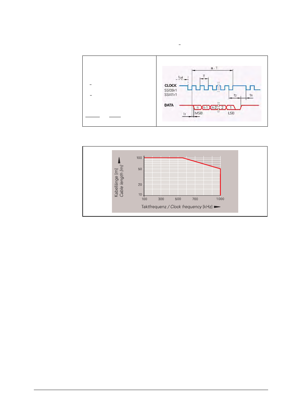
Permissible clock frequency with respect to cable lengths
Incremental signals
Some encoders also provide incremental signals. These are usually used to increase the
resolution of the position value, or to serve a second subsequent electronics unit. In general
these are 1 V
PP
incremental signals. Exceptions can be seen from the order designation:
SSI41 Hx with HTL incremental signals
SSI41 Tx with TTL incremental signals
For these the encoder-internal subdivision of the incremental signal is indicated by the order
designation:
Ha, Ta:
2-fold interpolation
Hb, Tb:
without interpolation
Hc:
scanning signals x 2
Data transfer
T = 1 to 10 µs
t
cal
See Specifications
t
1
0.4 µs (without cable )
t
2
= 17 to 20 µs
t
R
5 µs
n = Data word length
13 bits for ECN/ROC
25 bits for EQN/ROQ
CLOCK and DATA are not shown.
>
<
>