8 pwt test function – HEIDENHAIN PWM 20 User Manual
Page 179

182
HEIDENHAIN ATS Software User's Manual
6.2.8 PWT test function
The PWT test function is a mounting aid for various exposed encoders. It only supports analog
incremental interfaces (e.g. 1 Vpp, 11 µApp). The different signal parameters (amplitude height,
difference in amplitude, phase shift, on-to-off ratios, reference mark position, zero crossovers,
etc.) are displayed as bar diagrams.
The PWT function allows for a "rapid test" of analog incremental encoders.
For a detailed signal analysis, you have to activate the ATS analysis functions such as
the functions Analog, Recording and Counter.
The HEIDENHAIN test unit PWM 9 (in the PWM measuring mode) is also suitable for this
purpose.
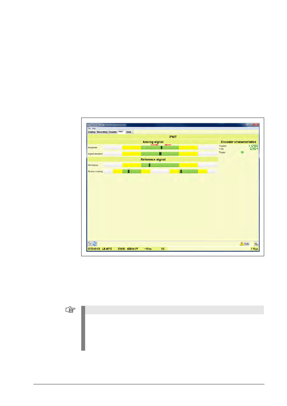
PWT screen display of a 1 Vpp output signal:
Basic elements of the PWT function:
Display through four bar diagrams
Drag indicators (red arrows) for min. and max. values
The tolerance ranges are displayed in three different colors:
Green = good; narrow tolerance range
Yellow = adequate; tolerance range within the specifications for the output signals
Gray = signal outside the specifications
Note
The green range is important for encoder mounting (exposed encoders) and for high-
precision applications.
The yellow range represents the tolerances in the HEIDENHAIN interface specifications
(see brochure "Interfaces of HEIDENHAIN Encoders" ID ID 1078628-xx or the chapter
"Interface description" in this manual).
For standard applications, all bars need to be within the yellow range.
