Bar for oscilloscope settings, Sampling rate and number of samples – HEIDENHAIN PWM 20 User Manual
Page 149
152
HEIDENHAIN ATS Software User's Manual
Bar for
oscilloscope
settings
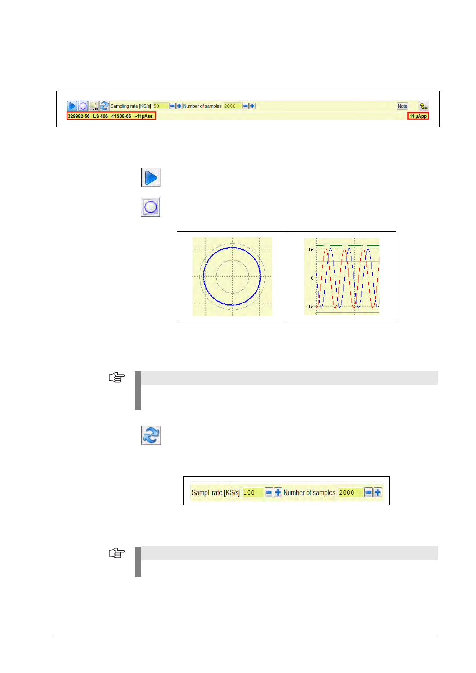
Database information (see red markings) of the connected encoder and interface type.
If the encoder was connected manually, only the interface is displayed.
The scale units of the coordinate axes depend on the display type and on the interface.
X-Y display:
Output signal in volts [V] or microamperes [µA]
Y-t display:
Y axis in volts [V] or microamperes [µA];
X axis in samples (number of samples)
Sampling rate
and
Number of samples
The functionalities of the fields "Sampling rate" and "Number of samples" are the same as those
of a digital oscilloscope. The sampling rate defines the rate at which the incremental signals are
converted; in "Number of samples" is specified, how many values are displayed on the screen.
Start/stop button = Start recording or stop (freeze) the screen display.
Button for X-Y or Y-t display = Display as circle function or as sine diagram
Note
In the X-Y view (also referred to as Lissajous figure or circular diagram), the inner green circle
represents the minimum amplitude, the outer green circle the maximum amplitude.
Reset button = Resets signal monitoring (Sig Mon) and the notes
Note
When you restart the function, the values are reset to default.