HEIDENHAIN PWM 20 User Manual
Page 172

November 2014
Checking incremental encoders
175
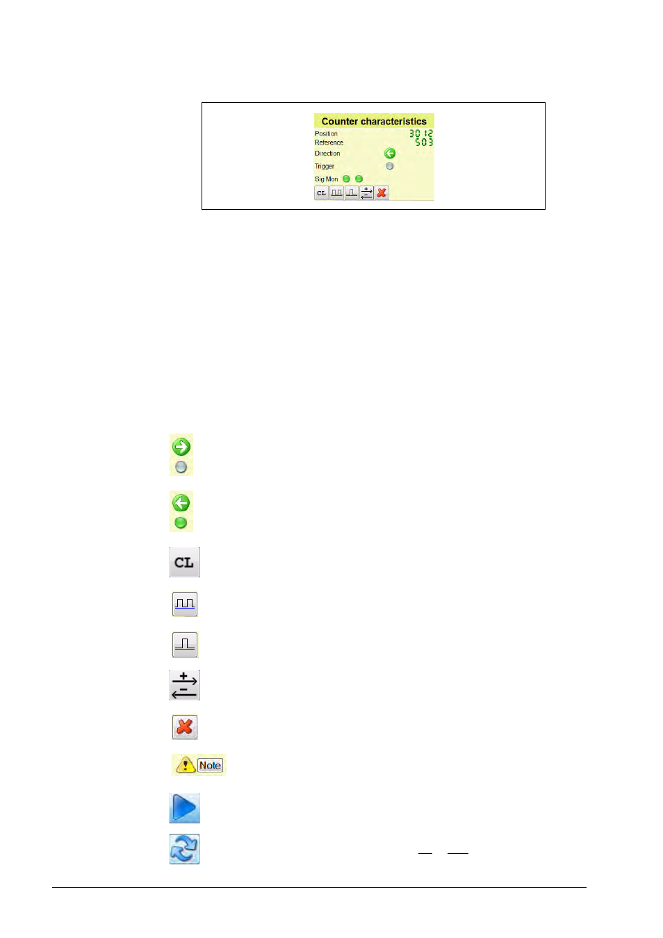
Explanation of the buttons and functions:
Counter and Position
The Counter display (large counting field) shows the measured value of the connected
encoder. Changes in the interpolation, grating period, line count, etc., influence the display value.
The smaller Position display always shows the grating periods (lines) that were counted
irrespective of whether settings were changed.
Reference
The Reference display shows the value between two reference marks.
(In the example, an ROD with 1000 lines is connected, and one revolution was made.)
Direction and Trigger
The arrow symbol shows the traversing direction of a linear encoder and the direction of rotation
of a rotary encoder.
The Trigger LED symbol turns green when a reference mark was detected (0.5 seconds hold
time). Gray LED = no reference mark was detected.
In the example:
Arrow right = positive counting values
No reference mark detected
Arrow left = negative counting values
Reference mark detected
Clears the display values of Counter and Position
Every reference mark clears Counter and Position
Counter and Position are cleared and restart with the next reference mark.
Change of counting direction
Clear the table and the graphics
Read the notes and repeat the measurement, if necessary.
Display stop (freeze)
Reset button = Resets signal monitoring (Signal Monitoring) and the notes
