Encoder characteristics, 3 level function – HEIDENHAIN PWM 20 User Manual
Page 196

November 2014
Checking incremental encoders
199
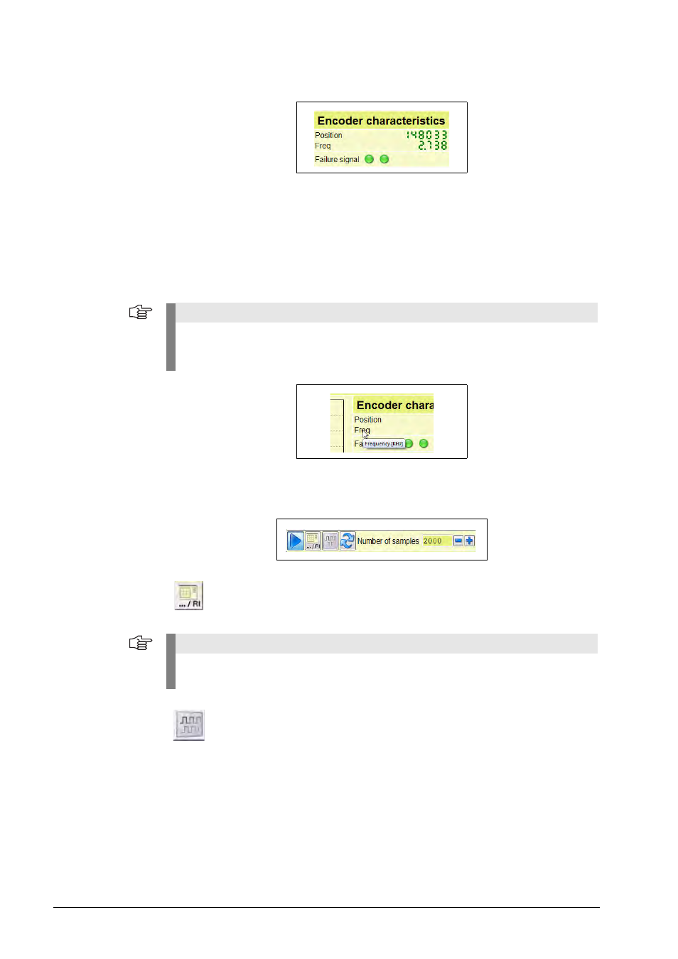
Encoder
characteristics
6.3.3 Level function
Bar of oscilloscope settings, TTL
Those function keys are described that are new or differ from those of the analog output signals.
Position:
The counter counts signal periods
Frequency:
Current input frequency
Failure signal
(-UaS):
"Left" LED =
Concurrent failure signal (red color only as long as
an error is present)"Right“ LED =
Failure signal is logged (display permanently red,
if an error was detected within the measuring range)
Note
The designations, scalings and units are automatically adapted to the connected encoder.
The meanings of the diagrams, curves and units can be seen from context menus; simply
move the cursor to the desired position, and the menu will open (see illustration below).
Reference trigger on/off: The reference signal is shown through a trigger LED.
The graphics display 3 shows the triggered, "frozen" reference pulse.
Note
This function has to be activated before ref. mark level measurement (bar display Ua0 H) is
possible! To make the reference mark known, the encoder must traverse it first.
TTL level measurement, positive/negative signals: Switch between inverted
and non-inverted output signals
