Input parameters – HEIDENHAIN iTNC 530 (340 49x-03) ISO programming User Manual
Page 471
HEIDENHAIN iTNC 530
471
9.3 Defining the Mac
h
ining Plane with
Pr
ojection Angles: PR
OJECTED
P
LANE
Input parameters
8
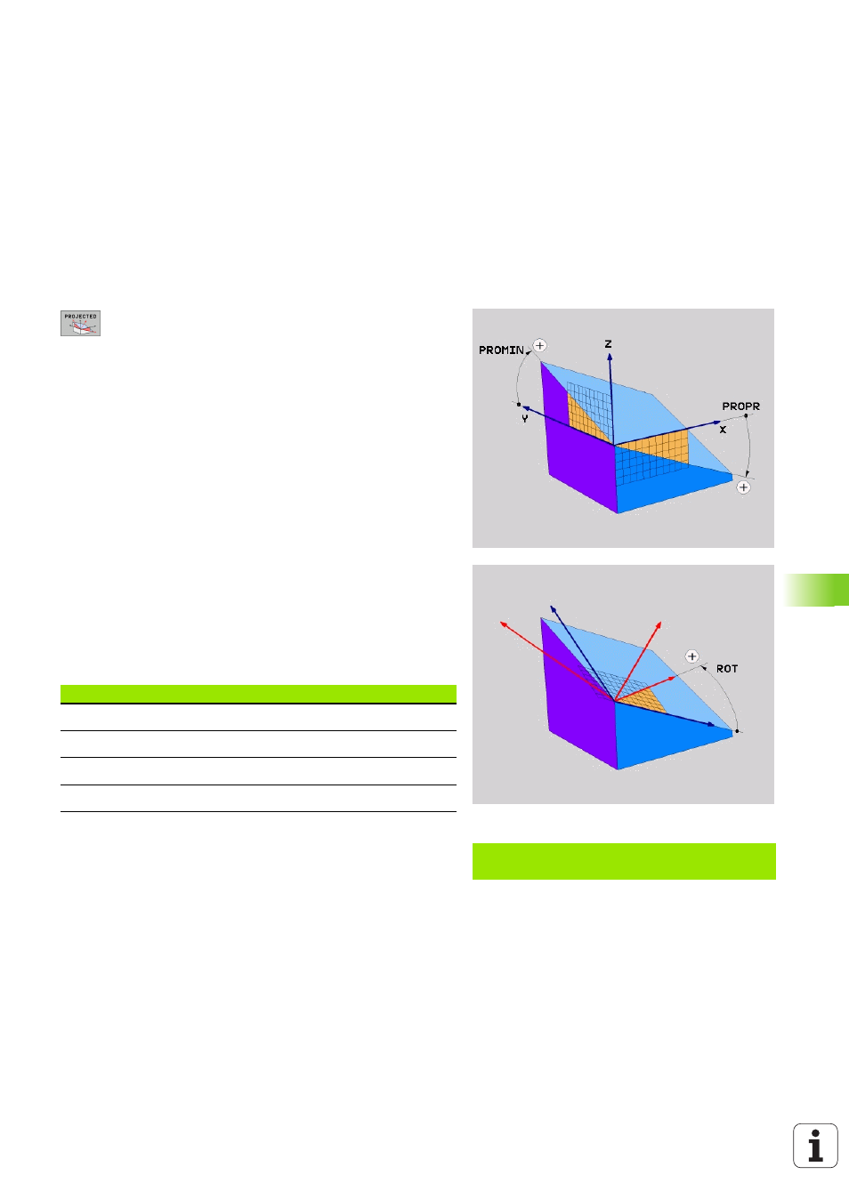
Proj. angle 1st coordinate plane?:
Projected angle
of the tilted machining plane in the 1st coordinate
plane of the fixed machine coordinate system (Z/X for
tool axis Z, see figure at top right). Input range: from
–89.9999° to +89.9999°. The 0° axis is the principal
axis of the active machining plane (X for tool axis Z.
See figure at top right for positive direction).
8
Proj. angle 2nd coordinate plane?:
Projected angle
in the 2nd coordinate plane of the fixed machine
coordinate system (Y/Z for tool axis Z, see figure at
top right). Input range: from -89.9999° to +89.9999°.
The 0° axis is the minor axis of the active machining
plane (Y for tool axis Z).
8
ROT angle of the tilted plane?:
Rotation of the
tilted coordinate system around the tilted tool axis
(corresponds to a rotation with Cycle 10 ROTATION).
The rotation angle is used to simply specify the
direction of the principal axis of the machining plane
(X for tool axis Z, Z for tool axis Y; see figure at bottom
right). Input range: from 0° to +360°.
8
Continue with the positioning properties (see
“Specifying the Positioning Behavior of the PLANE
Function” on page 482).
Abbreviations used
Example: NC block
N50 PLANE PROJECTED PROPR+24 PROMIN+24 PRO
ROT+30 ...
Abbreviation
Meaning
PROJECTED
Projected
PROPR
Principal plane
PROMIN
Minor plane
PROROT
Rotation