5 path contours-polar coordinates, Overview of path functions with polar coordinates, Zero point for polar coordinates: pole i, j – HEIDENHAIN iTNC 530 (340 49x-03) ISO programming User Manual
Page 231: 5 path contours—polar coordinates
HEIDENHAIN TNC iTNC 530
231
6.5 P
ath Cont
ours—P
olar Coor
dinat
es
6.5 Path Contours—Polar
Coordinates
Overview of path functions with polar
coordinates
With polar coordinates you can define a position in terms of its angle
H
and its distance R relative to a previously defined pole I, J (see
“Definition of pole and angle reference axis,” page 106).
Polar coordinates are useful with:
Positions on circular arcs
Workpiece drawing dimensions in degrees, e.g. bolt hole circles
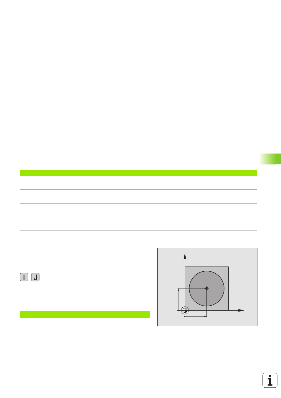
Zero point for polar coordinates: pole I, J
You can set the pole I, J at any point in the machining program, before
indicating points in polar coordinates. Set the pole in the same way as
you would program the circle center.
Programming
8
Enter Cartesian coordinates for the pole, or
if you want to use the last programmed position,
enter G29. Before programming polar coordinates,
define the pole. You can only define the pole in
Cartesian coordinates. The pole remains in effect until
you define a new pole.
Example NC blocks
Tool movement
Function
Required input
Page
Straight line at feed rate
Straight line at rapid traverse
G10
G11
Polar radius, polar angle of the straight-line
end point
Circular path in clockwise direction
Circular path in counterclockwise direction
G12
G13
Polar angle of the circle end point
Circular path corresponding to active direction
of rotation
G15
Polar angle of the circle end point
Circular arc with tangential connection to the
preceding contour element
G16
Polar radius, polar angle of the arc end point
X
Y
X=I
Y=J
N120 I+45 J+45 *