Absolute and incremental workpiece positions, 1 f u ndam e n tals – HEIDENHAIN iTNC 530 (340 49x-03) ISO programming User Manual
Page 107
HEIDENHAIN iTNC 530
107
4.1 F
u
ndam
e
n
tals
Absolute and incremental workpiece positions
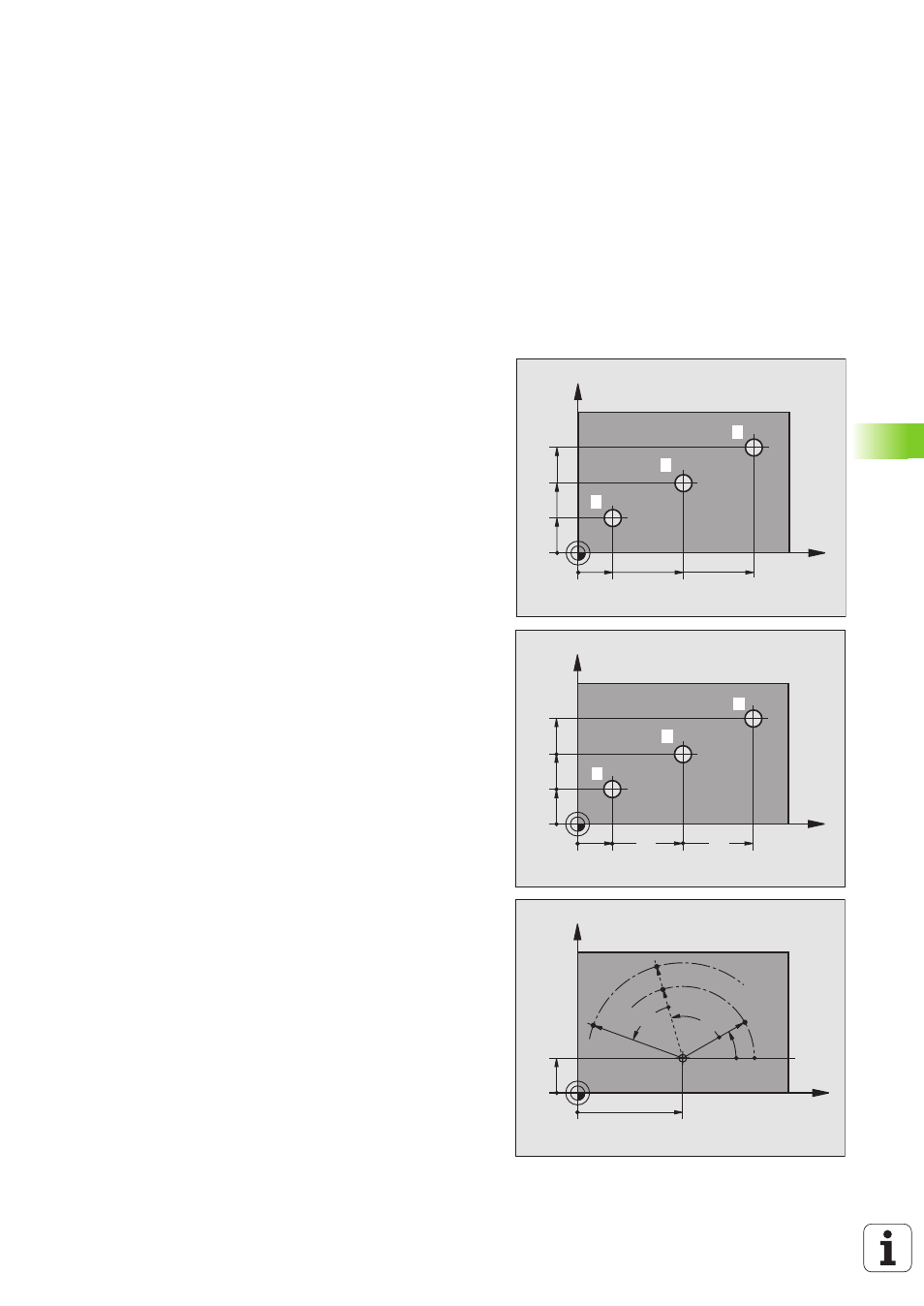
Absolute workpiece positions
Absolute coordinates are position coordinates that are referenced to
the datum of the coordinate system (origin). Each position on the
workpiece is uniquely defined by its absolute coordinates.
Example 1: Holes dimensioned in absolute coordinates
Incremental workpiece positions
Incremental coordinates are referenced to the last programmed
nominal position of the tool, which serves as the relative (imaginary)
datum. When you write a part program in incremental coordinates,
you thus program the tool to move by the distance between the
previous and the subsequent nominal positions. This is why it is also
referred to as a chain dimension.
To program a position in incremental coordinates, enter the function
G91
before the axis.
Example 2: Holes dimensioned in incremental coordinates
Absolute coordinates of hole
4
X = 10 mm
Y = 10 mm
Absolute and incremental polar coordinates
Absolute polar coordinates always refer to the pole and the reference
axis.
Incremental coordinates always refer to the last programmed nominal
position of the tool.
X
Y
30
20
50
30
10
10
2
1
3
Hole
1
Hole
2
Hole
3
X = 10 mm
X = 30 mm
X = 50 mm
Y = 10 mm
Y = 20 mm
Y = 30 mm
X
Y
20
10
10
20
10
10
5
4
6
Hole
5
, with respect to
4
Hole
6
, with respect to
5
G91 X
= 20 mm
G91 X
= 20 mm
G91 Y
= 10 mm
G91 Y
= 10 mm
X
Y
0°
30
10
CC
R
H
G91+H
R
R
G91+H
G91+R