Ami (auxiliary machine interface)(x51) (optional), Ii – 2 installation set u p – HEIDENHAIN PT 880 User Manual
Page 126
126
II Technical Information
II – 2 Installation Set
u
p
AMI (Auxiliary Machine Interface)(X51)
(Optional)
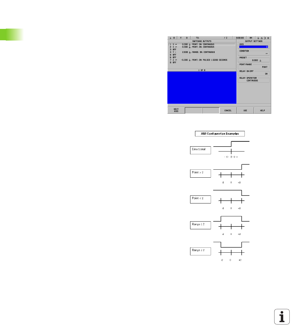
If the IOB 89 Option Box is connected to the POSITIP 880, the
SWITCHING OUTPUTS form will be available from the installation
setup list box. The IOB 89 hardware may be configured with 8 output
relays. See Fig. II.20.
To configure an individual relay output, move the cursor to the relay
number and press ENT. To remove a relay’s setting, highlight the relay
and press CE.
8
The AXIS field is used to specify which axis position controls the
relay. The axis is selected by pressing the NEXT AXIS soft key.
The DIRECTIONAL soft key is used to select the directional signal
mode. When selected, the relay’s operation is based on the position
value’s sign. The relay is activated when the value is non-negative.
The relay is de-activated when the value is negative. If
DIRECTIONAL is selected, the axis selection may be set to ALL
AXES. In this configuration, the relay’s output is set when an
operation sets any of the distance-to-go mode display values.
8
The CONDITION field is used to specify the required relationship
between the current position display and the switching point. It is
set by pressing the soft keys.
8
The PRESET field is used to define the switching points and to
select whether the point is an actual value or distance-to-go
position. The position source is selected by pressing one of the soft
keys.
8
The POINT/RANGE field is used to define whether the condition
refers to a point on the axis or refers to range about zero. If a range
is specified, the sign of the value is ignored.
8
To fill in the RELAY ON/OFF field press the OFF or ON soft keys.
When the condition has been satisfied the relay will turn OFF or ON.
Fig. II.20 AMI form
Fig. II.21 AMI form