General field/form navigation guide, Axes configuration, Ii – 2 installation set u p – HEIDENHAIN PT 880 User Manual
Page 117

POSITIP 880
117
II – 2 Installation Set
u
p
General field/form navigation guide
Press Up/Down arrow keys to move between fields.
Use keypad to enter numeric values within each field.
Press ENT to confirm the entry within a field.
Press USE when form is completed and save settings to the form.
Press USE NEW SETTINGS to return to the INFO screen.
Axes Configuration
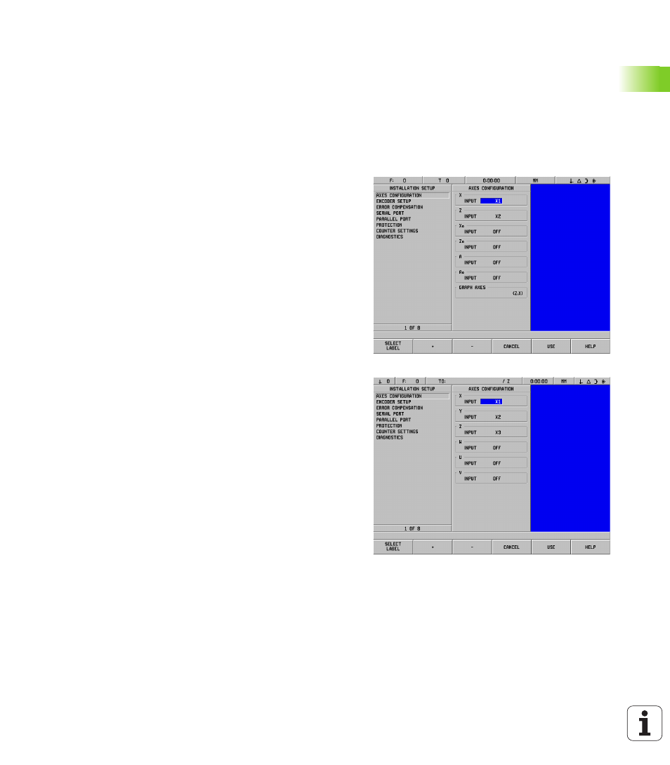
The configuration parameter allows encoder inputs (X1-X6) to be
assigned to displayable axes. The axis may consist of a single encoder
input or may be a combination of two encoders (2nd encoder position
added or subtracted from the 1st). See Fig. II.8 & Fig. II.9.
This is also where the labels for the axes may be changed (A-Z).
To set up the configuration of each axes:
8
Cursor to AXES CONFIGURATION in the INSTALLATION SETUP
menu and press ENT.
8
The AXES CONFIGURATION form is displayed.
8
Use the numeric keys 1-6 to select the corresponding encoder input
for the axis.
8
Press the CE key to remove the encoder input and OFF will be
displayed. Which ever encoders are not being used should be
switched to the OFF position at this point.
8
Two encoder inputs can be coupled to an axis by using the numeric
keys and the “+” and “-” soft keys.
8
Press the SELECT LABEL soft key to bring up the SELECT LABEL
character chooser form and the LEFT, RIGHT, SELECT CHARACTER,
CANCEL
and USE soft keys are available.
8
Use the LEFT and RIGHT soft keys and the Up and Down arrow keys
to highlight the desired character.
8
Press the SELECT CHARACTER soft key or ENT hard key to select the
character as the axis label and remove the SELECT LABEL form. The
soft keys will return to the previous soft key menu.
8
When you have finished entering values, press the USE soft key or
the ENT hard key to save the changes for that parameter and return
to the INSTALLATION SETUP menu.
8
Graph axes functions are for turning functions only. The default
setting for graph axes is to display the Z axis coordinates along the
horizontal axis of the part graphic and the X axis coordinates along
the vertical axis. If your configuration differs from this, press the
HORIZONTAL
or VERTICAL soft keys to select the appropriate axes.
Fig. II.8
AXES CONFIGURATION form (turning)
Fig. II.9
AXES CONFIGURATION form (milling)
