Grass Valley 8943RDA User Manual
Page 34
34
8943RDA/-D/-DFR — Instruction Manual
Configuration
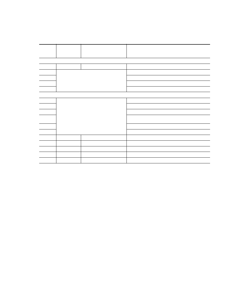
Table 9. Local Onboard Configuration Functions
Function
Switch
Position
Paddle
Switch
Up
Paddle
Switch
Down
Function Description
Input Op Mode
0
–
–
Neutral position. Leave S1 in this position during normal operation.
1
AUTO BYP,
AUTO RC,
3G,
HD,
SD, or
BYPASS
Set Input Operation Mode for Channel 1
2
Set Input Operation Mode for Channel 2
3
Set Input Operation Mode for Channel 3 (8943RDA-DFR only)
4
Set Input Operation Mode for Channel 4 (8943RDA-DFR only)
Source Select
5
CH1 (J9 for 8943RDA/-D and J10 for 8943RDA-DFR)),
CH2 (J10 for 8943RDA-D or J8 for 8943RDA-DFR),
CH3 (Fiber 1 input
1
8943RDA-DFR only),
or CH4 (Fiber 2 input
2
8943RDA-DFR only)
1
Presence of CH3 Fiber 1 input requires an optional Dual Receiver submodule.
2
Presence of CH4 Fiber 2 input requires an optional Dual Receiver or Transceiver submodule.
Select input source to coax output pair J1/J2
6
Select input source to coax output pair J3/J4
7
Select input source to coax output pair J5/J6
8
Select input source to coax output pair J7/J8 (8943RDA-D) or
select input source to single coax output J7 (8943RDA-DFR)
9
Select input source to Fiber 1
3
TX output (8943RDA-DFR only)
3
Presence of Fiber 1 TX output requires an optional Dual Transmitter submodule.
A
Select input source to Fiber 2
4
TX output (8943RDA-DFR only)
4
Presence of Fiber 2 TX output requires an optional Dual Transmitter or Transceiver submodule.
B
Enable
Disable
Channel 1 reporting
C
Enable
Disable
Channel 2 reporting
D
Enable
Disable
Channel 3 reporting
E
Enable
Disable
Channel 4 reporting
F
Recall
Recall Factory Defaults