8943rda-dfr module cabling – Grass Valley 8943RDA User Manual
Page 24
24
8943RDA/-D/-DFR — Instruction Manual
Cabling
8943RDA-DFR Module Cabling
The 8943RDA-DFR requires the 89003FR-R rear module with electrical
inputs and outputs and a fiber optic connector for connection of fiber
inputs and outputs depending on the type of fiber optic option submodule
installed.
If using an optional fiber optic submodule, it must be installed on the front
of the 8943RDA-DFR front module. Fiber optic submodule types available
are listed with installation instructions in
Fiber Optics Submodule Installation
Electrical and fiber video input to electrical video output pair and fiber
output mapping is done in configuration using the local onboard controls,
Settings web page, or Newton control panel (
).
and
for 89003FR-R cabling information.
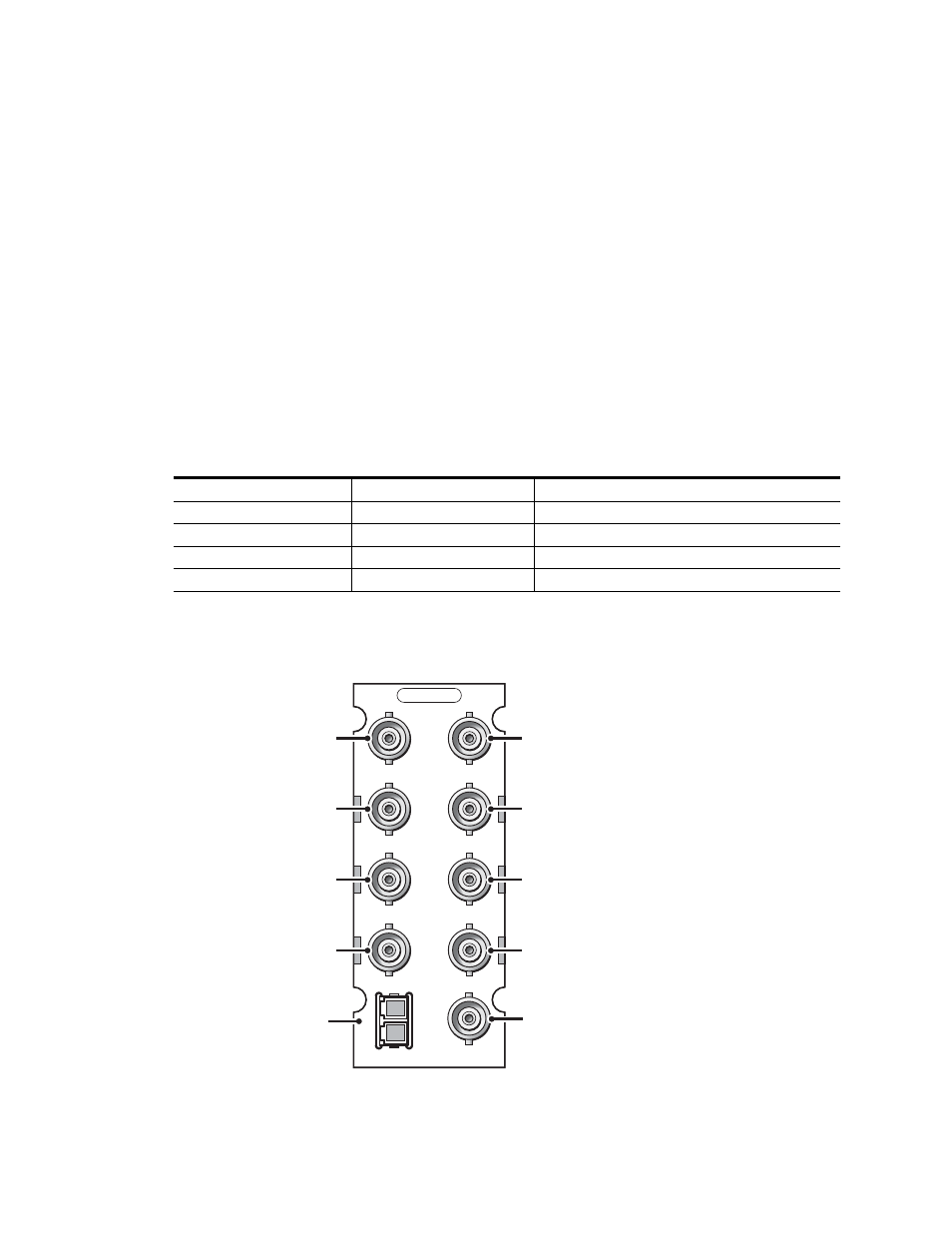
Figure 13. 8943RDA-DFR Cabling on 89003FR-FR Rear Module
Table 4. 8943RDA-DFR Cabling for 89003FR-R and Fiber Optic Connections
Fiber Optic Submodule
Input(s) Available
Outputs Available
None
BNC J10, BNC J8
BNC pairs: J1/J2, J3/4, J5/J6, J7
Dual Fiber Receiver
BNC J10, BNC J8, Fiber 1, Fiber 2
1
1
Input to output pair assignment is made on Settings web page where Fiber inputs must be enabled.
BNC pairs: J1/J2, J3/4, J5/J6, J7
Dual Fiber Transmitter
BNC J10, BNC J8
BNC pairs: J1/J2, J3/4, J5/J6, J7, Fiber Out 1, and Fiber Out 2
2
2
Input to output pair assignment is made on Settings web page where Fiber outputs must be enabled.
Fiber Transceiver
BNC J10, BNC J8, Fiber In 2
1
BNC pairs: J1/J2, J3/4, J5/J6, J7, and Fiber Out 1
2
89003FR-R
8592_03
r0
J1
J2
J3
J4
J5
J6
J7
1
2
J8
J10
FIBER
Out
Out
Out
Out
In
Out
Out
Out
In
Fiber I/O
Connector