Video outputs, 8943rda module cabling – Grass Valley 8943RDA User Manual
Page 22
22
8943RDA/-D/-DFR — Instruction Manual
Cabling
Video Outputs
The 8943RDA model outputs conform to the video standards listed in the
output specifications in
. The electrical video outputs
are available in four pairs, J1/J2, J3/J4, J5/J6, J7/J8 (J7 only for the
8943RDA-DFR). Fiber optic outputs available (Fiber 1 and Fiber 2) depend
on the type of fiber optic submodule installed. Two Fiber optic outputs are
available when a dual transmitter fiber optic submodule is installed and
one fiber optic output (TX1) is available when a transceiver is installed.
Video input to video output pair(s) mapping is done in configuration using
the local onboard controls, Settings web page, or Newton control panel
(
).
Electrical outputs are always enabled. Fiber optic outputs on the
8943RDA-DFR module must be enabled in configuration using the local
onboard controls, Settings web page, or Newton control panel (
).
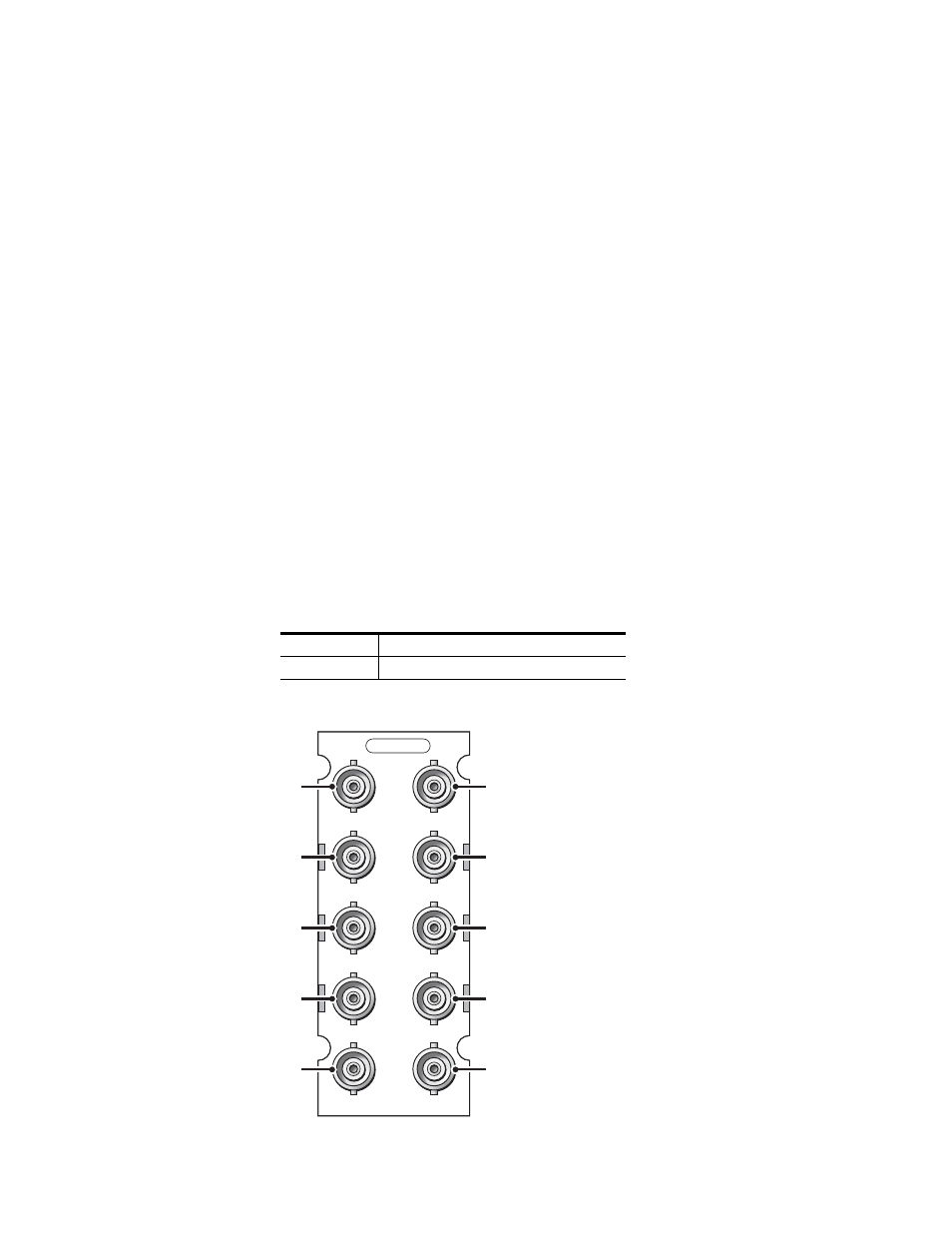
8943RDA Module Cabling
The 8943RDA front module requires the 89003E-R rear module. This
module has one electrical input to eight electrical BNC outputs. Refer to
for 89003E-R cabling information.
Figure 11. 8943RDA Cabling on 89003E-R Module
Table 2. Cabling Inputs and Outputs for 8943RDA Module
Signal Input
Outputs Available
J9 BNC
BNC Pairs: J1/J2, J3/J4, J5/J6, J7/J8:
J1
J2
J3
J4
J5
J6
J7
J8
J9
J10
Out
Out
Out
Out
Out
Out
Out
Out
Not Used
In
89003E-R
8592_01
r0