Local onboard configuration – Grass Valley 8943RDA User Manual
Page 33
8943RDA/-D/-DFR — Instruction Manual
33
Configuration
Local Onboard Configuration
Local onboard configuration can be done for the following:
•
CH1-4 OUTPUT OP MODE
– set the output operating mode for each available
channel (
•
CH1-4
OUTPUT SOURCE
– set
input source to each available output (
•
Enable TX Outputs (8943RDA-DFR only)
– when a dual transmitter or trans-
ceiver fiber optic submodule is installed on the 8943RDA-DFR, the
output(s) must be enabled by setting jumper J13, TX OPT, to pins 1-2.
Setting jumper J13 to pins 2-3 disables the transmitter outputs.
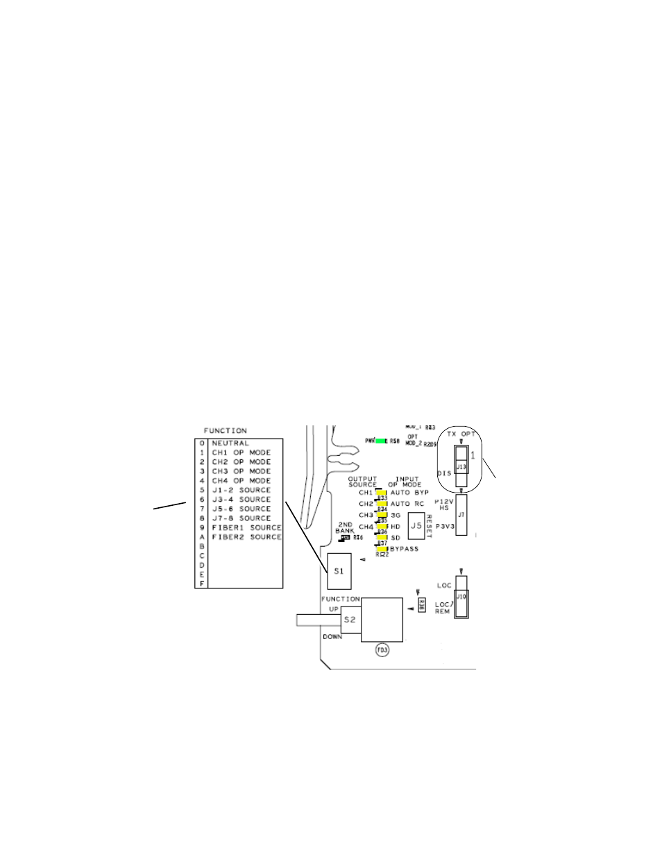
Local onboard controls include two switches: the FUNCTION rotary
switch, S1, and the paddle switch, S2, on the front edge of the module.
These are used in conjunction with the OUTPUT SOURCE and INPUT OP
MODE LEDs shown on the right of
.
The parameters coordinating to the FUNCTION switch settings are silk-
screened on the back of the module as shown on the left of
Use the figure below and the settings in
to set each of the
module parameters.
Figure 15. Local Onboard Controls Rear Silkscreen and Front LEDs
Silkscreen on back
of module corresponding
to settings on S1.
Set jumper J13 to pins 1-2
to enable fiber TX outputs
(8943RDA-DFR only).