Input to output mapping – Grass Valley 8943RDA User Manual
Page 32
32
8943RDA/-D/-DFR — Instruction Manual
Configuration
Input to Output Mapping
Another configuration parameter available with the 8943RDA-D and the
8943RDA-DFR is the input to output mapping capability. Any available
input channel can be routed (mapped in configuration) to any available
output through the internal crosspoint structure. This crosspoint mapping
configuration allows flexibility in choosing what input channels feed what
output pairs.
The 8943RDA-D input channel sources, CH1 (Coax J9) and CH2 (Coax J10)
can be mapped to any of the four coaxial output pairs, J1/J2, J3/J4, J5/J6,
and J7/J8. For example, the input source on CH1 can be mapped to feed
output pair J1/J2 and the input source on CH2 can be mapped to feed
output pairs J3/J4, J5/J6, and J7/J8.
In the case of the 8943RDA-DFR, input channel sources are CH1 (Coax J10),
CH2 (Coax J8), CH3 (Fiber 1), and CH4 (Fiber 2). Fiber input channels and
outputs are available depending on the type of SFP fiber optic submodule
option installed. Fiber inputs and outputs must be enabled in configura-
tion. Refer to
for a list of the fiber optic submodule
option models available.
8943RDA-DFR input to output mapping with the available SFP fiber optic
submodules is summarized in
. Also refer to the block diagrams
starting on
for an illustration of each 8943RDA-DFR configuration.
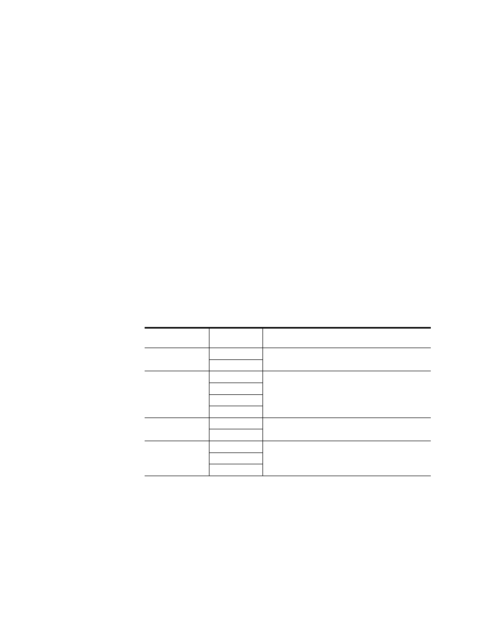
Table 8. 8943RDA-DFR Input to Output Mapping
Fiber Optic
Submodule
Input(s)
Available
Outputs Available
None
CH1 (BNC J10)
BNC pairs: J1/J2, J3/4, J5/J6, J7 (single output)
CH2 (BNC J8)
Dual Fiber Receiver
CH1 (BNC J10)
BNC pairs: J1/J2, J3/4, J5/J6, J7 (single output)
CH2 (BNC J8)
CH3 (Fiber 1)
1
1
Input to output pair assignment is made on Settings web page where Fiber inputs must be enabled.
CH4 (Fiber 2)
1
Dual Fiber Transmitter
CH1 (BNC J10)
BNC pairs: J1/J2, J3/4, J5/J6, J7 (single output), Fiber Out 1,
and Fiber Out 2
2
2
Input to output pair assignment is made on Settings web page where Fiber outputs must be enabled.
CH2 (BNC J8)
Transceiver
CH1 (BNC J10)
BNC pairs: J1/J2, J3/4, J5/J6, J7 (single output), and Fiber Out 1
2
CH2 (BNC J8)
CH 3 (Fiber In 2
1