Sundance SMT390-VP User Manual
Page 44
Version 2.4
Page 44 of 55
SMT390-VP User Manual
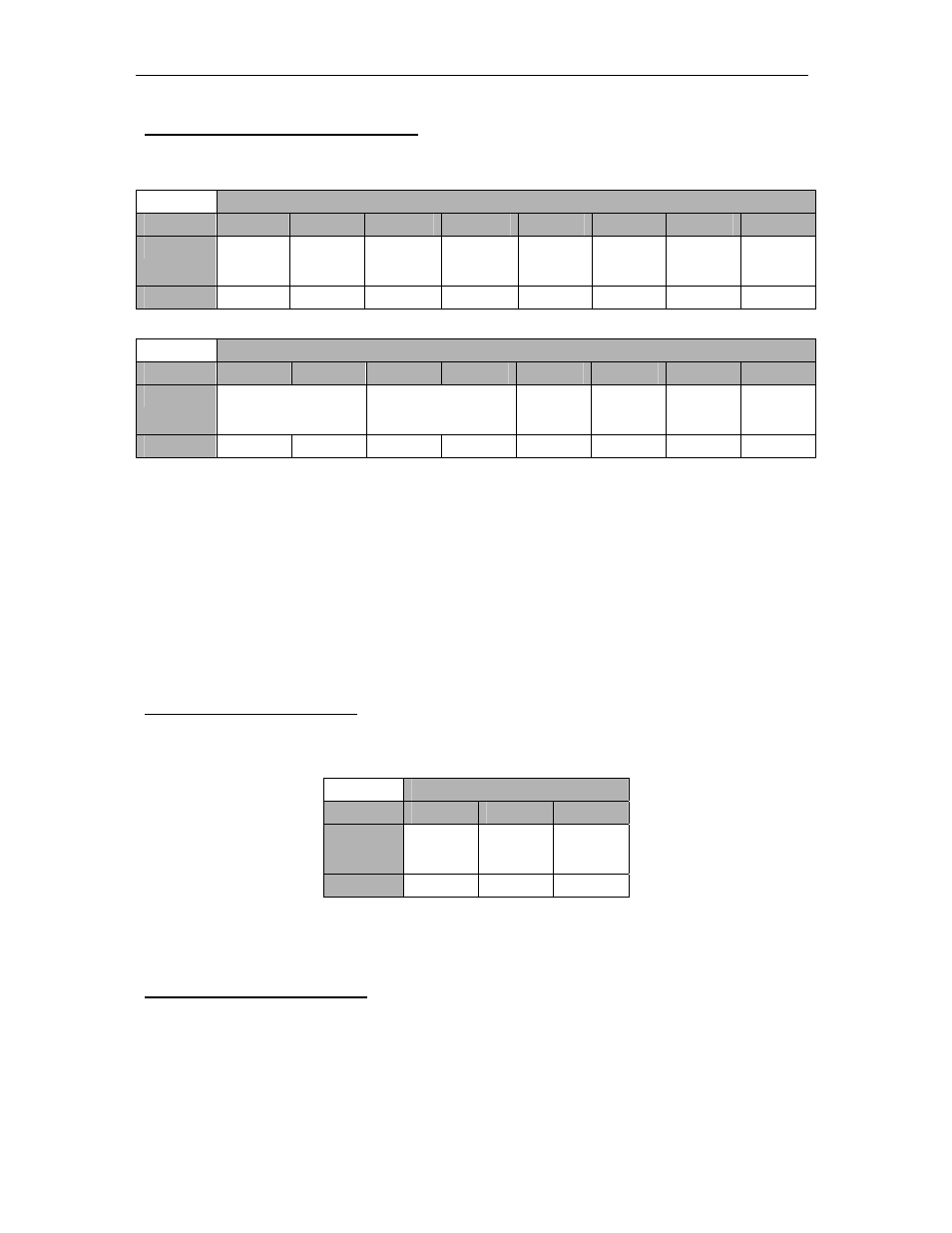
ADC Setup Control Register (0x07)
The ADC Setup Control Register sets the configuration settings of the ADC that is
configurable by the user.
ADC Setup Register
Byte
Bit 15
Bit 14
Bit 13
Bit 12
Bit 11
Bit 10
Bit 9
Bit 8
Description
Not Avail.
Not Avail
Not Avail
Not Avail
Not Avail
Not Avail
Out of
range
Channel B
Out of
range
Channel A
Default
Not Avail.
Not Avail.
Not Avail.
Not Avail.
Not Avail.
Not Avail.
‘0’
‘0’
ADC Setup Register
Byte
Bit 7
Bit 6
Bit 5
Bit 4
Bit 3
Bit 2
Bit 1
Bit 0
Description
Output Selection
Channel B
Output Selection
Channel A
Scale
Channel B
Data
Format
Channel B
Scale
Channel A
Data
Format
Channel A
Default
‘0’ ‘0’ ‘0’ ‘0’ ‘0’ ‘0’ ‘0’ ‘0’
Figure 28 – ADC Setup Control Register (0x07).
Data Format
: ‘0’ for binary format and ‘1’ for 2’s complement format.
Scale
: ‘0’ for half scale and ‘1’ for full scale.
Output Selection
: ‘00’ for channel disable, ‘11’ for counter and ‘10’ for ADC.
Out of range:
The SMT390-VP offers the possibility of outputting a 16-bit counter instead of
samples coming from the ADCs. This can be used to check if data are lost on a data
path for example.
Decimation Register (0x08)
The decimation Register sets the decimation settings for both channels A and B.
Decimation Register
Byte
Bits 31-16
Bits 15-8
Bits 7-0
Description
Not Avail.
Decimation
value
Channel B
Decimation
value
Channel A
Default
Not Avail.
0
0
Figure 29 – Decimation Register (0x08).
Decimation value: value from 0, 3, 4, 5, 6… 15
SHB Control Register (0x09)
The SHB Control register is only available when SHB Half-word (16-bits)
configuration is used.