Diagram key, Figure 7 - clock structure – Sundance SMT390-VP User Manual
Page 18
Version 2.4
Page 18 of 55
SMT390-VP User Manual
SHB Interface
The retrieved data from the ‘Retrieve from Memory’ block is transmitted over the SHB
interface. The SHB interface controls the SHB bus between the SMT390-VP and any
module connected to the SHB requesting the data.
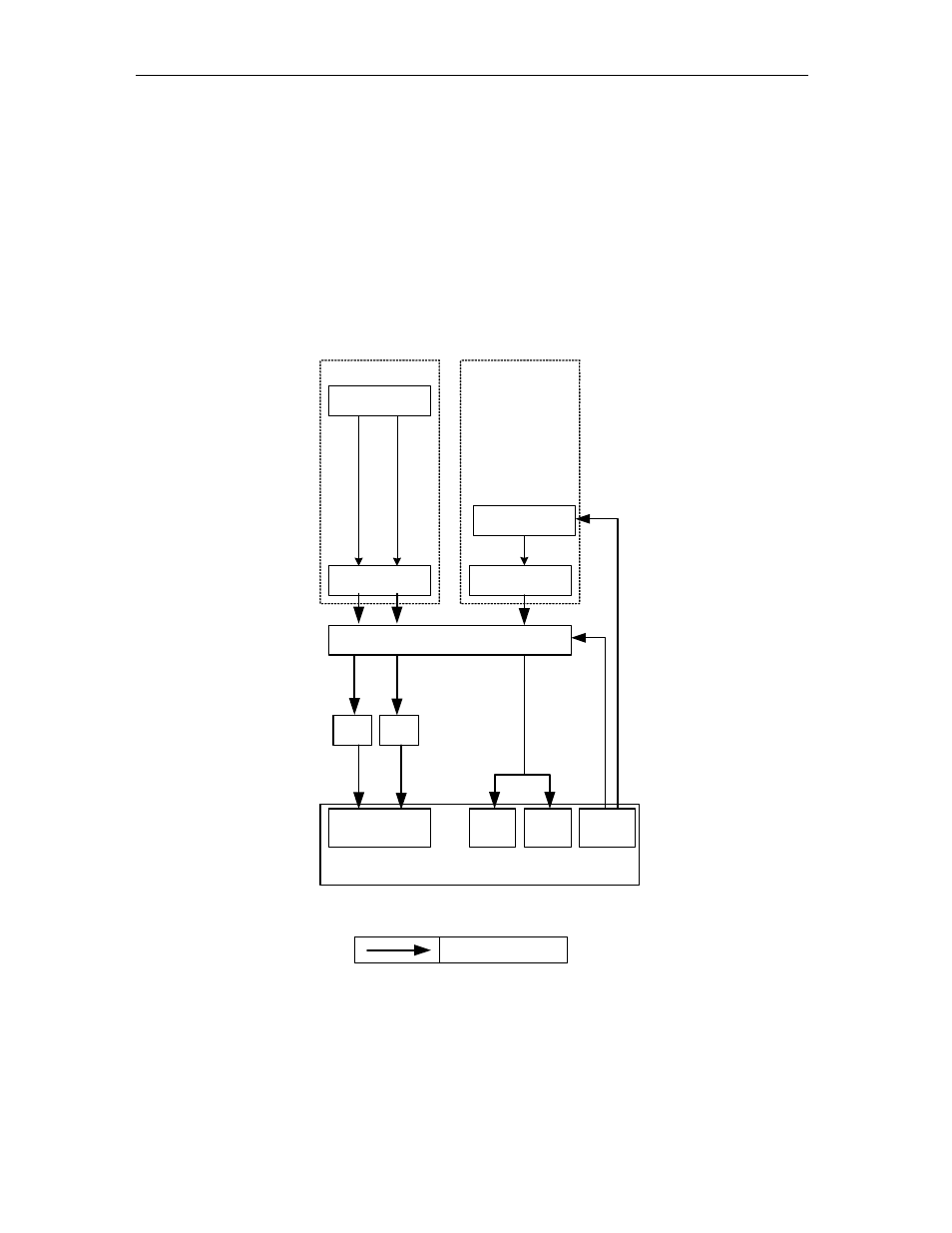
Clock Structure
There is an integrated clock generator on the module. The user can either use this
clock or provide the module with an external clock (input via MMCX connector). The
RSL interface will only function if the module’s integrated clock is used (RSL are not
available).
External Clocks
Module Clock
FPGA
Clock synthsizer
Clock
Control
TTL to LVPECL
LVPECL
Buffers
External Clock Inputs
(MMCX)
4:2 Mux with Dual Output
ADCA
Ch
A
C
lo
ck
Ch
B
C
lo
ck
LVDS
SerDes
Clock
Sys
Clock
DLL
RSL
Clock
DLL
Diagram Key:
210 MHz LVPECL Clock
ADCB
Figure 7 - Clock Structure.
- SMT107 (16 pages)
- SMT6035 v.2.2 (39 pages)
- SMT6012 v.4.6 (22 pages)
- FC100 (12 pages)
- FC108 v.1.1 (10 pages)
- SMT6065 v.4.0 (45 pages)
- FFT v.2.1 (19 pages)
- SMT111 (18 pages)
- SMT118LT (10 pages)
- SMT118 (20 pages)
- SMT123-SHB (13 pages)
- SMT128 (15 pages)
- SMT145 (18 pages)
- SMT148 (35 pages)
- SMT130 v.1.0 (46 pages)
- SMT148FX (48 pages)
- SMT310Q (55 pages)
- PARS (70 pages)
- SMT166-FMC (52 pages)
- SMT166 (44 pages)
- SMT300Q v.1.6 (61 pages)
- SMT310 v.1.6 (50 pages)
- SMT317 (24 pages)
- SMT326v2 (24 pages)
- SMT338 (19 pages)
- SMT349 (32 pages)
- SMT339 v.1.3 (27 pages)
- SMT338-VP (22 pages)
- SMT358 (25 pages)
- SMT351T (37 pages)
- SMT351 (25 pages)
- SMT350 (45 pages)
- SMT362 (30 pages)
- SMT365G (23 pages)
- SMT364 (37 pages)
- SMT373 (15 pages)
- SMT368 (24 pages)
- SMT370v3 (46 pages)
- SMT377 (22 pages)
- SMT381 2007 (31 pages)
- SMT381-VP (81 pages)
- SMT387 (42 pages)
- SMT391 (18 pages)
- SMT384 (47 pages)