Sundance SMT390-VP User Manual
Page 31
Version 2.4
Page 31 of 55
SMT390-VP User Manual
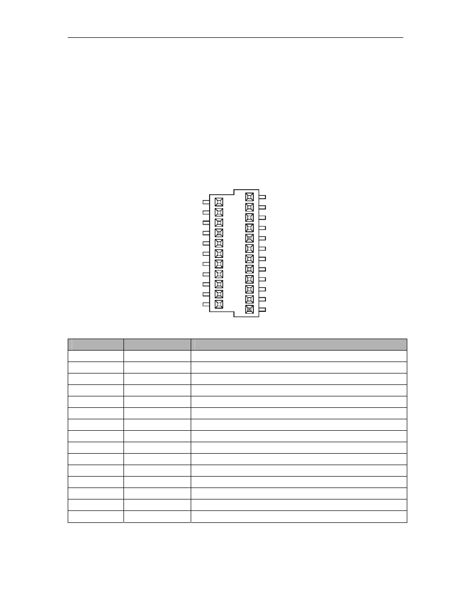
The mated height between the main module and the daughter card is 5 mm.
Each pin on the power connector (33 pins in total) can carry 1.5 A. Digital +12V
(D+12V0), -12V (D-12V0), 5V (D+5V0), 3V3 (D+3V3) and digital ground (DGND) are
provided over this connector. D+3V3 and D+5V0 are assigned four pins each. The
daughter card can thus draw a total of 6A of each of these two supplies. The integral
ground plane on the differential connector provides additional grounding.
Some JTAG Lines are also mapped onto this connector to be used in case the
Daughter module would have a TI Processor. They would allow debugging and
programming via JTAG.
The following table shows the pin assignment on the power connector:
2
1
33
Pin Number
Pin Name
Description of Signal
1
D+3V3
Digital 3.3 Volts
2 DGND Digital
Ground
3
D+3V3
Digital 3.3 Volts
4 DGND Digital
Ground
5
D+3V3
Digital 3.3 Volts
6 DGND Digital
Ground
7
D+3V3
Digital 3.3 Volts
8 DGND Digital
Ground
9
D+5V0
Digital 5.0 Volts
10 DGND Digital
Ground
11
D+5V0
Digital 5.0 Volts
12 DGND Digital
Ground
13
D+5V0
Digital 5.0 Volts
14 DGND Digital
Ground
15
D+5V0
Digital 5.0 Volts