Setting-up an acquisition – Sundance SMT390-VP User Manual
Page 38
Version 2.4
Page 38 of 55
SMT390-VP User Manual
SMT390-VP
can work in two modes depending on the firmware downloaded in the
FPGA: SHB Half word (16-bits) or 32-bits SHB full word (32-bits).
SHB full word configuration
In this case both channels are output each on one SHB connector. ADC Channel A is
output on SHB B and ADC channel B on SHB A.
SHB half word configuration
In this case both channels are output on the same SHB connector. It can be SHB A
or SHB B depending on the value of bit 0 of the SHB Control Register.
Data will be available on the SHB as follow:
• Channel A will be output on the higher part of the bus
• Channel B will be output on the lower part of the bus
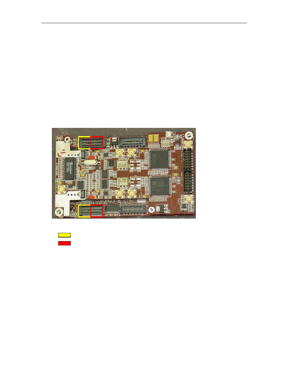
Figure 21: SMT390-VP channels output
: High part of bus
: Low part of bus
Setting-up an acquisition
• FPGA’s configuration: see “Configuring the FPGA” section for more details.
• Initialize SMT390-VP’s registers with the requested values. See Control
Register Settings section for the description of the registers.
• Start
the
acquisition:
SMT390-VP
is waiting for a trigger command to start the
acquisition. This command can come either from external trigger connectors or
from ComPort 3 (see acquisition trigger register section for more information).
• Once it receives a trigger command, SMT390-VP will grab data coming from
daughter module and store them into internal memory.