Main module daughter card, Figure 8 – power generation and distribution – Sundance SMT390-VP User Manual
Page 20
Version 2.4
Page 20 of 55
SMT390-VP User Manual
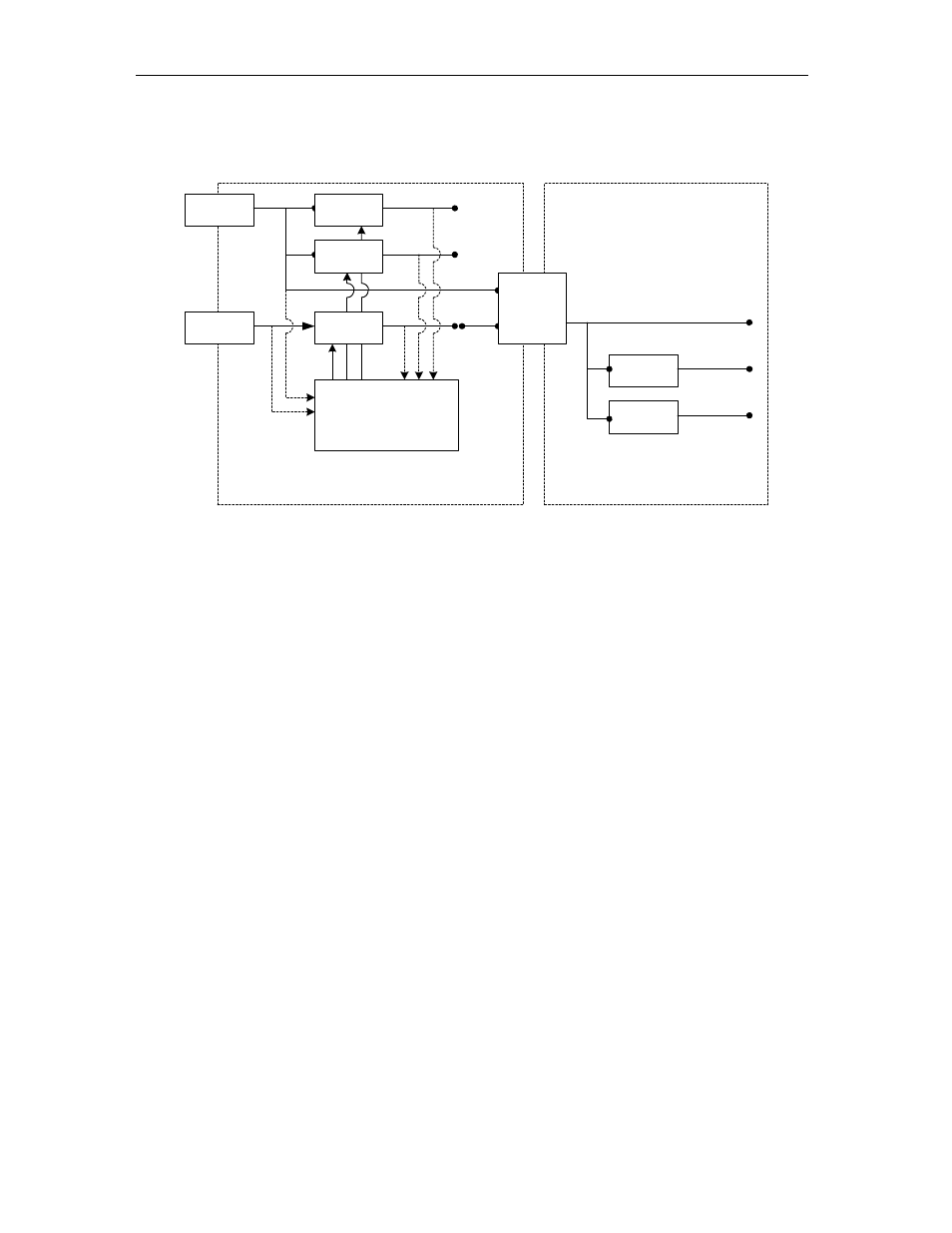
The MSP430 distributes the reset to the daughter board. The following diagram
illustrates the power distribution and the reset distribution on the SMT390-VP:
Main Module
Daughter Card
TIM Connector
D+5V0_IN
D+3V3
TIM
Mounting Hole
D+3V3_IN
Analog Power
Switch
D+2V5
D+1V5
Main Module to
Daughter Card
Power
Connector
D+3V3
Analog Filter
Vadcio
DC / DC
Converter
A+3V3
D+2V25
MSP430
Microprocessor
Vccint
DC / DC
Converter
Vccaux
DC / DC
Converter
On / Off
Control
Voltage
Measure
Voltage
Measure
Figure 8 – Power Generation and Distribution
MSP430 Functionality
The MSP430 implements analog control functionality that is difficult to implement in
the FPGA. The microprocessor
• Controls the power start-up sequence
• Controls the reset structure on the module
The following diagram shows what the default microcontroller boot code does:
- SMT107 (16 pages)
- SMT6035 v.2.2 (39 pages)
- SMT6012 v.4.6 (22 pages)
- FC100 (12 pages)
- FC108 v.1.1 (10 pages)
- SMT6065 v.4.0 (45 pages)
- FFT v.2.1 (19 pages)
- SMT111 (18 pages)
- SMT118LT (10 pages)
- SMT118 (20 pages)
- SMT123-SHB (13 pages)
- SMT128 (15 pages)
- SMT145 (18 pages)
- SMT148 (35 pages)
- SMT130 v.1.0 (46 pages)
- SMT148FX (48 pages)
- SMT310Q (55 pages)
- PARS (70 pages)
- SMT166-FMC (52 pages)
- SMT166 (44 pages)
- SMT300Q v.1.6 (61 pages)
- SMT310 v.1.6 (50 pages)
- SMT317 (24 pages)
- SMT326v2 (24 pages)
- SMT338 (19 pages)
- SMT349 (32 pages)
- SMT339 v.1.3 (27 pages)
- SMT338-VP (22 pages)
- SMT358 (25 pages)
- SMT351T (37 pages)
- SMT351 (25 pages)
- SMT350 (45 pages)
- SMT362 (30 pages)
- SMT365G (23 pages)
- SMT364 (37 pages)
- SMT373 (15 pages)
- SMT368 (24 pages)
- SMT370v3 (46 pages)
- SMT377 (22 pages)
- SMT381 2007 (31 pages)
- SMT381-VP (81 pages)
- SMT387 (42 pages)
- SMT391 (18 pages)
- SMT384 (47 pages)