Venus x1 back panel, Cont interface, Dial switch – RGBLink VENUS X1 User Manual User Manual
Page 27: 10/100m udp interface, Usb interface, Hardware orientation
2. Hardware Orientation
VENUS X1 Back Panel
VENUS X1 User Manual 27
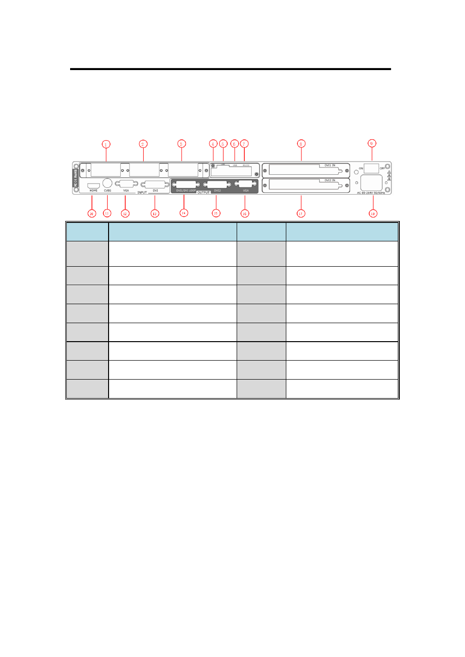
The figure below illustrates the professional interface and control signals of
VENUS X1 back panel.
NO
INTERFACE
NO
INTERFACE
1. 2. 3
S. V. D. C. U. H and Audio
Optional Module
11
CVBS Input BNC
4
Dial Switch
12
VGA Input DB15
5
10/100M Interface
13
DVI Input DVI-I
6
USB Interface
14
DVI/DVI LOOP Output DVI-I
7
RJ11 (RS232) Interface
15
DVI Output DVI-I
8. 17
Sending card interface
16
VGA Output DB15
9
Switch
18
Power IEC-3 port
10
HDMI Input HDMI-A
CONT Interface
4: Dial Switch
If the two dial switches are upwards, the device is in normal work, and if
they are downwards, the device is in upgrade state. OLED module light is
off when the device is in upgrade state. Some of the button lights turn on,
and the device will not work.
5: 10/100M UDP Interface
Used to connect the windows control program or device upgrade.
6: USB Interface
Used to connect the windows control program or device upgrade.