RGBLink CP 2048 User Manual
Dazzle cp 2048 quick start
Add: S603-604 Weiye Building Torch Hi-Tech Industrial Development Zone Xiamen, Fujian Province, P.R.C
Tel: 00865925771197
Fax: 00865925771202
Email: [email protected] Website:
DAZZLE CP 2048 Quick Start
DSK setup
Set up DSK to an active layer.
PIP setup
Set up multiple pictures/ overlay pictures presentation.
Preview setup
Set up the size and effects of Preview output via CP 2048.
17
18
19
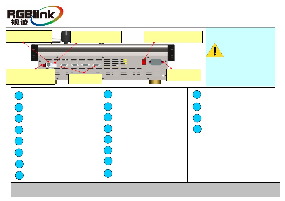
Lan Port
Connect to an isolated network.
Used for communications with
devices.
USB Control Port
Connect to an isolated communication.
Used for communications with devices.
Toggle Switch
Switch downward to be “ON” state, it
works normally; Switch upward to be
“OFF” state, it is updating;
AC Power Port
AC power source AC 85-
264V 50/60Hz IEC-3.
Switch
Switch ON, indicator light, power on,
Switch OFF, indicator light off, power off.
RS232 Port
Used for communications
with devices
Background setup
Set up the background sources.
20
This product is intended to
operate from a power
source between 85~264
volts rms. This product is
only workable under correct
power condition and well
grounded state. First to set
up the IP of controlled devices
to be correct without repetition;
when system power on, set up
the IP or COM ports of all
controlled devices to ensure all
devices communicating well.
System power on
AC 85-264V 50/60Hz IEC-3 power port
switch ON, indicator light, power on.
switch OFF, indicator light off, power off.
Touch screen calibration
Calibrate the Controller’s Touch Screen display.
Factory reset
Perform a complete factory reset on all controlled devices.
IP setup
Set up IP of the to be controlled device via touch
screen.
Router setup
Set up your system’s routing switchers to choose IP.
RS232 setup
Set up RS232 of the to be controlled device via touch
screen.
1
2
6
5
4
3
T-BAR lock
Lock for use, and unlock to use.
7
8
Z-axis lock
Joystick lock for use, and unlock to use.
Output format setup
Configure the output format via CP 2048.
Program setup
Set up the size and effects of Program output via CP
2048.
Save the setup
Save the state of the Controller in non-volatile memory
Load save modes
Load the save modes to the controlled devices.
Operation destination setup
Set up the system’s operation destinations, include Aux.
Programming setup
Program input signal of the controlled devices via
CP2048.
Buttons lock
Lock for use, and unlock to use.
Low voltage “script” light switch
Switch to control low voltage “script” light
9
10
11
12
13
14
15
16