Serial poll status byte, Te…… 89 – Measurement Computing DAC488 v.1 User Manual
Page 95
DAC488 User’s Manual
DAC488 Commands 89
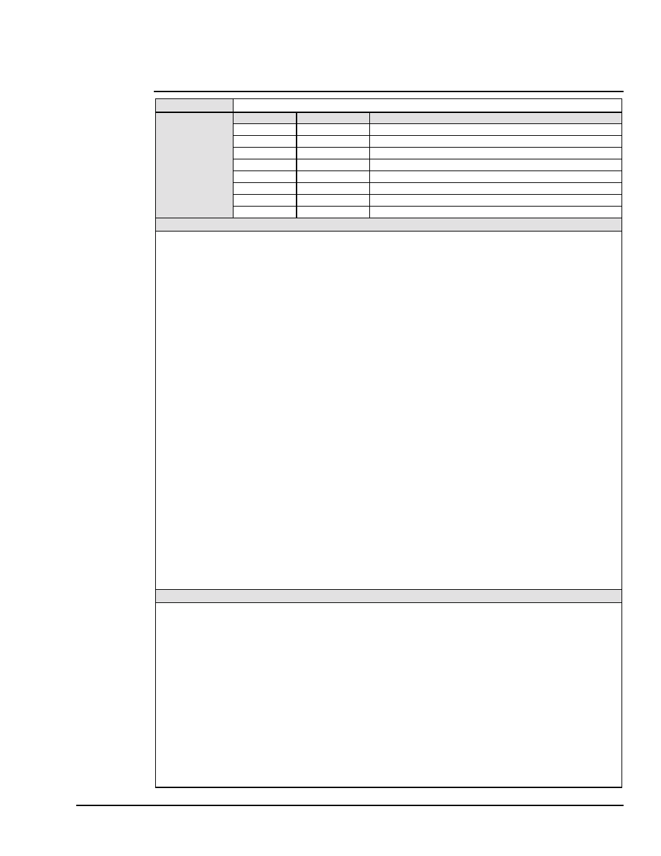
Serial Poll Status Byte
TYPE
Command Support
SUMMARY
Bit Location
Decimal Value
Description
DIO1
1
(LSB) DAC port 1 ready for trigger.
DIO2
2
DAC port 2 ready for trigger.
DIO3
4
DAC port 3 ready for trigger. (DAC488/4 only)
DIO4
8
DAC port 4 ready for trigger. (DAC488/4 only)
DIO5
16
Trigger Overrun.
DIO6
32
Error.
DIO7
64
Service Request bit.
DIO8
128
(MSB) External Trigger Input Transition.
DESCRIPTION
The Serial Poll Status byte is sent upon receiving the Serial Poll (SPOLL) command from the controller. Refer to the
Service Request Mask (Mmask) command description for details on how the Serial Poll byte is affected. To enable
each bit to reflect the true status of the device, the appropriate Mmask command must be executed. The significance
of each bit in the Serial Poll Status byte is shown below:
•
DIO1: When enabled by the M1 command, DIO1 is set when DAC port 1 can accept a trigger. DIO1 is cleared if
the port is not ready or is generating a waveform in the Waveform (C3) mode.
•
DIO2: When enabled by the M2 command, DIO2 is set when DAC port 2 can accept a trigger. DIO2 is cleared if
the port is not ready or is generating a waveform in the Waveform (C3) mode.
•
DIO3: When enabled by the M3 command, DIO3 is set when DAC port 3 can accept a trigger. DIO3 is cleared if
the port is not ready or is generating a waveform in the Waveform (C3) mode. If the DAC488/2 is being Serial
Polled, a zero will always be returned in this bit position.
•
DIO4: When enabled by the M4 command, DIO4 is set when DAC port 4 can accept a trigger. DIO4 is cleared if
the port is not ready or is generating a waveform in the Waveform (C3) mode. If the DAC488/2 is being Serial
Polled, a zero will always be returned in this bit position.
•
DIO5: The DIO5 bit is set when the DAC488 receives a trigger while processing a previous trigger. The bit is
cleared by executing the Overrun Status (U6) or the Error Query (E?) commands and then reading the response.
•
DIO6: The DIO6 bit is set when any one of the error conditions (listed under the Error Query command) occurs.
This bit is cleared by executing an Error Query (E?) or Status (U0) command.
•
DIO7: The DIO7 bit will be set when the DAC488 generates a Service Request (SRQ). This is used by the
controller to determine that the Service Request was generated by the DAC488. This bit is cleared when the
DAC488 is Serial Polled.
•
DIO8: The DIO8 bit is set when an external trigger pulse is received on the external trigger/SRQ input and the
DAC488 is properly armed. This bit is cleared when the DAC488 is Serial Polled.
EXAMPLE (Using a DAC488/4)
PRINT#1,"OUTPUT09;S0 X"
Line 1: Restore the factory power on defaults.
PRINT#1,"CLEAR09"
Line 2: Reset the DAC488.
PRINT#1,"OUTPUT09;M32 X"
Line 3: Select SRQ on error.
PRINT#1,"OUTPUT09;P7 X"
Line 4: Send an invalid bus command. ERROR and SRQ LEDs should
illuminate.
PRINT#1,"SPOLL09"
Line 5: Serial Poll Status byte returned will be 111 (64 + 32 + 8 + 4 + 2 + 1).
The interpretation of this Serial Poll Status byte is as follows:
•
64: The DAC488 was the source of the SRQ.
•
32: There was an error.
•
08: Port 4 is ready for a trigger.
•
04: Port 3 is ready for a trigger.
•
02: Port 2 is ready for a trigger.
•
01: Port 1 is ready for a trigger.
When the DAC488 is Serial Polled, the SRQ LED will turn off.