Waveform control mode, Ode…… 29 – Measurement Computing DAC488 v.1 User Manual
Page 35
DAC488 User’s Manual
DAC488 Operation 29
The commands required to load the internal buffer for this example are:
PRINT#1,"OUTPUT09;C2 P1 F0,3 L0 Q1 X"
PRINT#1,"OUTPUT09;B1,1X B2,3X B2,4X"
PRINT#1,"OUTPUT09;L0 X"
•
Line 1:
C2
selects Stepped Control mode,
P1
selects port 1,
F0,3
defines a buffer with the first
location as location 0 and the number of values in the sequence to 3,
L0
sets the location pointer back
to 0 (first location) and
Q1
enables port 1 to trigger on an external trigger.
•
Line 2:
B1,1X
selects the
±
1 volt range, 1 volt for first point,
B2,3X
selects the
±
5 volt range, 3 volts
for second point and
B2,4X
selects the
±
5 volt range, 4 volts for third point.
•
Line 3:
L0
sets the location pointer back to location 0 before the port is triggered. If this is not done,
the location pointer will start at location 3, not location 0.
The output of the sequence is controlled by the rate at which external triggers occur. In the graph
previously shown, each T represents an external trigger event.
Waveform Control Mode
The Waveform control mode may be used to control the
DAC in an automatic manner. A buffer is defined using
the Buffer Definition (
F
) command and voltage values
are loaded into the buffer using the Buffer Location (
L
)
command and the Buffer Data (
B
) command. Once the
DAC488 is triggered, these preloaded voltage values
are then output at a regular interval. The time interval
between the output of each value is set by using the
Interval (
I
) command. The number of cycles of the
waveform is set by using the Number of Cycles (
N
)
command.
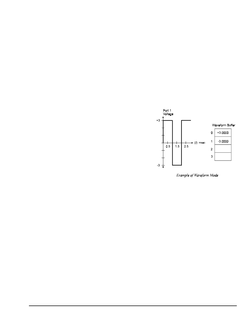
One application of waveform mode may be to use the
DAC488 as a precise function generator. The
waveform example shows how the DAC488 would be
configured to output a 6 volt peak to peak 500 Hz
square wave centered at zero.
More complex waveforms may be generated by loading the buffer with values computed using a high-level
language program. Sample programs are included with the DAC488 which will load the buffer with voltage
values to generate a Sine, Triangle, Ramp and other waveforms.
The commands required to load the internal buffer for this example are:
PRINT#1,"OUTPUT09;C3 P1 F0,2 G1 L0 I1 X"
PRINT#1,"OUTPUT09;B2,3X B2,-3X N0 X"
PRINT#1,"OUTPUT09;L0 X"
PRINT#1,"OUTPUT09;TRIGGER"
•
Line 1:
C3
selects Waveform control mode,
P1
selects port 1,
F0,2
defines a buffer with the first
location as location 0 and the number of points in the sequence to 2,
G1
selects trigger on
GET
,
L0
sets
the location pointer to 0 (the first location) and
I1
sets the time interval between points to 1
millisecond.
•
Line 2:
B2,3X
selects the
±
5 volt range, 3 volts for first point and
B2,-3X
selects the
±
5 volt range, -3
volts for second point,
N0
sets the number of cycles to continuous.
•
Line 3:
L0
sets the buffer location pointer back to location 0 before the port is triggered. If this is not
done, the location pointer will start at location 2, not location 0.
•
Line 4: When the IEEE Group Execute Trigger is executed, the DAC488 will output the waveform at
port 1 continuously.