Part ii: automatic calibration process – Measurement Computing DAC488 v.1 User Manual
Page 54
48 DAC488 Calibration
DAC488 User’s Manual
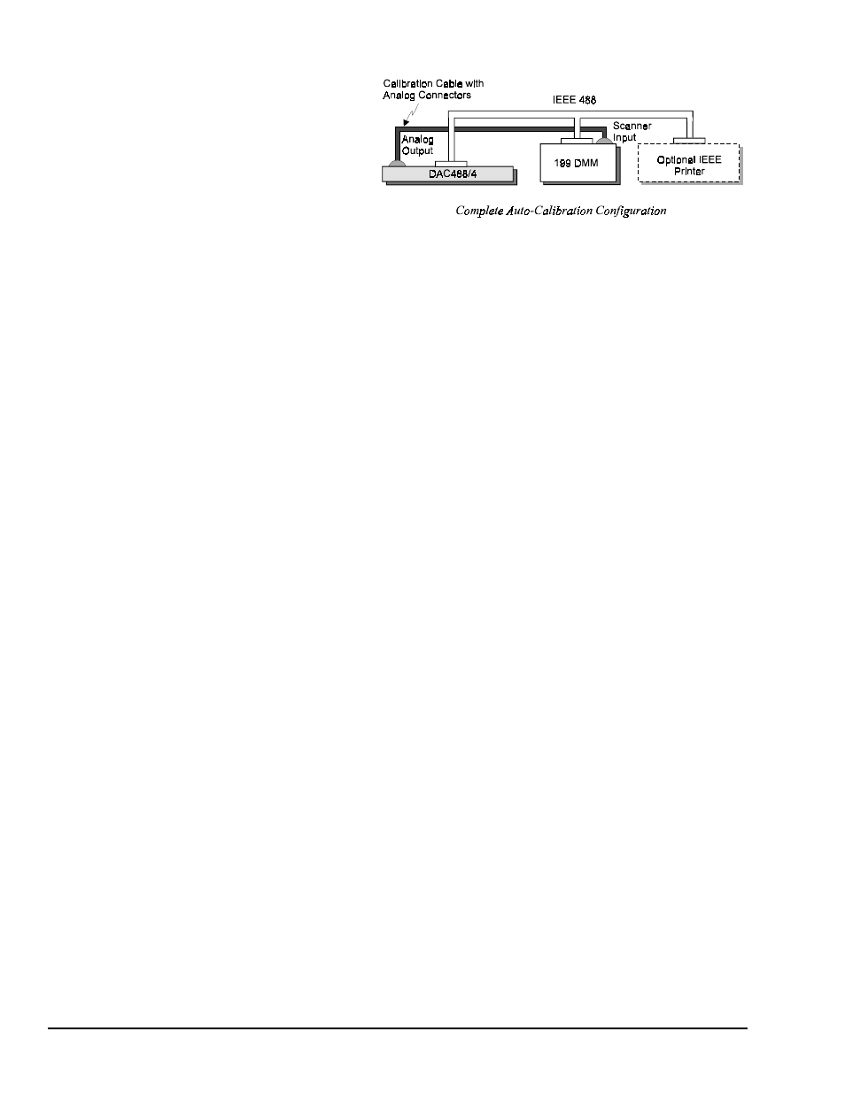
4. Once the calibration cable has
been made, the analog output of
all DAC488 ports can then be
connected to the 199, to complete
the configuration in the following
figure.
Part II: Automatic Calibration Process
When power is applied to the DAC488, its TEST LED will flash indicating that auto-calibration is taking
place, then will turn off when the calibration has finished. If any errors occur during calibration the
ERROR LED will flash and the calibration procedure will be aborted.
During auto-calibration, several messages will be displayed on the 199 in upper case characters. Each
message will be displayed for 2 seconds. The messages will be displayed in the same order as listed below:
1.
DAC488/4:
This message is displayed if the DAC488/4 is properly connected to the 199, or:
DAC488/2:
This message is displayed if the DAC488/2 is properly connected to the 199.
2.
AUTO_CAL:
This message is displayed after message 1 to show that the DAC488 is in auto-calibration
mode.
3.
NO_SCANNER:
This message is displayed if the 199 does not have a scanner installed.
4.
NO_CONNECT:
This message is displayed if the calibration cable is not connected or the wiring is
incorrect.
5.
CALIBRATE:
This message is displayed if the calibration enable switch is in the depressed position
which will allow the new Calibration Constants to be saved in the Non-Volatile RAM.
6.
CAL_OFF:
This message is displayed if the calibration enable switch is not in the depressed position.
The DAC488 will not perform the auto-calibration. However, the present Calibration Constants will be
used in the verify procedure. This approach may be used to verify the calibration of the unit without
recalibrating it.
7.
VERIFY:
This message is displayed when the DAC488 has finished calibrating all ports and is ready
to print a calibration verification report. If a printer is connected, a verification report is printed listing
all voltages tested. Any failures are noted on the report. A summary report is also printed which lists
the Calibration Constants for each port and range.
8.
NO_PRINTER:
This message is displayed if the DAC488 does not find a printer connected at bus
address 5.
9.
CAL_PASSED:
This message is displayed if no errors occur during the verification tests.
10.
CAL_FAILED:
This message is displayed if any errors occur during the verification tests.
Note:
All lines sent to the printer are terminated with a carriage return (
CR
).