Measurement Computing DAC488 v.1 User Manual
Page 16
10 DAC488 Setup
DAC488 User’s Manual
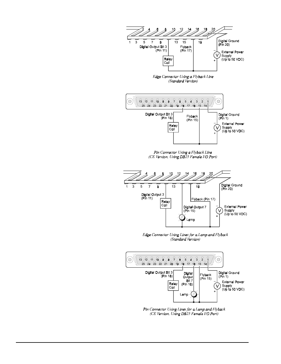
When used with relays or solenoids,
the Flyback pin on the edge card
connector should be connected to
the positive supply lead of the power
supply used with the external
devices being driven, as shown in
the following figures. To configure
the digital output lines for this
purpose, it is necessary to open the
enclosure and reposition the
configuration jumper. For
instructions on how this is done, see
section To Configure the Digital
Output Lines in the following text.
Once the digital output lines have
been configured for high level
operation, they can be used to drive
devices such as relays, solenoids and
displays. For example, a typical
application may require a lamp and
a relay to be driven by the Standard
version DAC488. For this example,
the relay is connected to digital
output pin 11 and the lamp is
connected to digital output pin 15,
as shown in the following diagram.
Using this same example for the CE
version DAC488, the relay is
connected to digital output pin 18
and the lamp is connected to digital
output pin 16, also shown in the next
diagram.
Since a relay is used for this
application, the Flyback terminal is
connected to the positive terminal of
the external power supply. Note
also that the Ground lead of the
power supply should be connected
to pin 20 (Digital Ground) on the
Standard card edge connector, or to
pin 1 (Digital Ground) on the CE
pin connector.