Hardware setup, Front & rear panel layouts, Outs…… 6 – Measurement Computing DAC488 v.1 User Manual
Page 12
6 DAC488 Setup
DAC488 User’s Manual
Hardware Setup
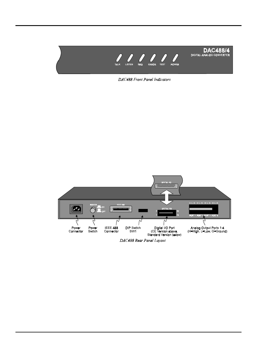
Front & Rear Panel Layouts
Six LED indicators on the DAC488 front panel, display the unit status. The following list describes the
functions of these indicators:
•
TALK: ON when DAC488 is in the Talker state; OFF when in the Idle or Listener state.
•
LISTEN: ON when DAC488 is in the Listener state; OFF when in the Idle or Talker state.
•
SRQ: ON when DAC488 generated a service request; OFF when no SRQ is pending.
•
ERROR: ON when an error has occurred; OFF when no error condition exists.
•
TEST: ON when used in conjunction with the Test (
W
) command to verify that communication has
been established with the DAC488. The TEST LED will flash when the DAC488 is calibrating in the
auto-calibration mode. The TEST LED will then remain lit when finished calibrating in the auto-
calibration mode.
•
POWER: ON when power is being applied while the power switch is in the ON position; OFF when
power is not present.