Digital i/o port, Port…… 8 – Measurement Computing DAC488 v.1 User Manual
Page 14
8 DAC488 Setup
DAC488 User’s Manual
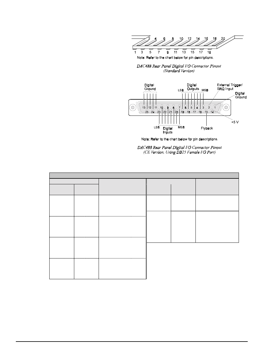
Digital I/O Port
The DAC488 has eight digital input
lines and eight digital output lines. At
power on, the configuration of digital
output lines is determined by the
options saved as the startup
configuration. In order to set the digital
output lines to a particular state upon
power on, the System Defaults (
S
)
command must be used after all the
lines have been configured. For
example, if it is desired to have digital
output line 1 set high and the other lines
set low at power on, the lines would be
set to this configuration using the
Digital Output (
D
) command. Then this
configuration would be saved using the
System Defaults (
S
) command.
Digital I/O Port Pinouts
Connector Pin
Connector Pin
Standard
(20-pin)
CE Version
(DB25)
Connector Pin
Description
Standard
(20-pin)
CE Version
(DB25)
Connector Pin
Description
1
23
Digital Input Bit 1 (LSB)
17
15
Flyback
2
10
Digital Input Bit 2
18
2
Ext. Trigger/SRQ Input
3
22
Digital Input Bit 3
19
14
+5 V (
≤
50 mA load)
4
9
Digital Input Bit 4
1
Digital Ground
5
21
Digital Input Bit 5
11
Digital Ground
6
8
Digital Input Bit 6
12
Digital Ground
7
20
Digital Input Bit 7
13
Digital Ground
8
7
Digital Input Bit 8 (MSB)
24
Digital Ground
9
19
Digital Output Bit 1 (LSB)
20
25
Digital Ground
10
6
Digital Output Bit 2
11
18
Digital Output Bit 3
12
5
Digital Output Bit 4
13
17
Digital Output Bit 5
14
4
Digital Output Bit 6
15
16
Digital Output Bit 7
16
3
Digital Output Bit 8 (MSB)