U - user status, Er status…… 81 – Measurement Computing DAC488 v.1 User Manual
Page 87
DAC488 User’s Manual
DAC488 Commands 81
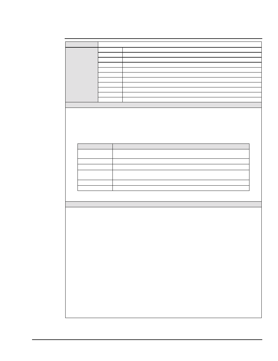
U - User Status
TYPE
System Command
SYNTAX
Un
Where
n = 0, 1, 2, 3, 4, 5, 6, 7,
or
8
.
U0
Send system status on talk.
U1
Send DAC port 1 status on talk.
U2
Send DAC port 2 status on talk.
U3
Send DAC port 3 status on talk. (DAC488/4 only)
U4
Send DAC port 4 status on talk. (DAC488/4 only)
U5
Send digital input port status on talk.
U6
Send Overrun status on talk.
U7
Send actual output voltage and range on talk.
U8
(Default) Send programmed output voltage and range on talk.
U?
Returns current status select setting.
DESCRIPTION
The User Status (Un) command will cause the DAC488 to send a status message when next addressed to Talk. U5
is used to read the digital input port. The Dval command is used to write to the digital output port. The status of the
DAC488 may be read at any time without interfering with normal operation. Any error conditions are cleared after the
status string is read by the controller.
The format of the status string returned by the DAC488 after receiving a Status command is as follows:
Command(s)
Returned Status String Format
U0
*.*D####E#G###K#M###O#P#Q###S#T###U#W#Y#
where the leading
information
*.*
is the revision number of the DAC488 firmware.
U1,U2,U3,U4
A#C#F#####,#####I#####L#####N#####P#R#V#.#####
U5
###
,
where
###
is the decimal value of the input lines.
U6
###
,
where
###
specifies the port which was overrun: 001 = port 1, 002 = port
2, 004 = port 3, 008 = port 4, 006 = ports 2 and 3, etc.
U7
C#P#R#V+##.#####,
where
V
is the actual output voltage
U8
A#C#P#R#V+##.#####,
where
V
is the programmed output voltage.
Note:
Each
#
equals the parameter(s) corresponding to that command.
EXAMPLE
PRINT#1,"CLEAR09"
Line 1: Reset the DAC488.
PRINT#1,"OUTPUT09;U0 X"
Line 2: Request the system status of the DAC488.
PRINT#1,"ENTER09"
INPUT#2,A$
Line 4: Read the status string.
PRINT A$
Line 5: Display:
*.*D####E#G###K#M###O#P#Q###S#T###U#W#Y#
where each # would show the current option in use for each command.
PRINT#1,"OUTPUT09;S0 X"
Line 6: Restore the factory defaults as the power on defaults
PRINT#1,"CLEAR09"
Line 7: Reset the DAC488. Issuing an IEEE Interface Clear (IFC) will set the
DAC488 to its power on state.
PRINT#1,"OUTPUT09;U2 X"
Line 8: Request the status of Port 2.
PRINT#1,"ENTER09"
INPUT#2,A$
Line 10: Read the status.
PRINT A$
Line 11: Status string returned will be:
A1C0F01024,01024I01000L01024N00001P2R0V+00.00000
with
the following data: Autorange on (A1), Direct Control mode (C0), First Buffer
Location is 1024, Buffer size is 1024 locations (F01024,01024), Interval is
1000 milliseconds (I01000), Buffer Location Pointer is 1024 (L01024),
Number of Cycles is 1 (N00001), Port 2 is the selected port (P2), Range is
Ground Range (R0) (the range will be Ground Range, if Autoranging is
disabled), and programmed output voltage is 0 volts (V+00.00000).