B - buffer data, B - buffer data…… 60 – Measurement Computing DAC488 v.1 User Manual
Page 66
60 DAC488 Commands
DAC488 User’s Manual
B - Buffer Data
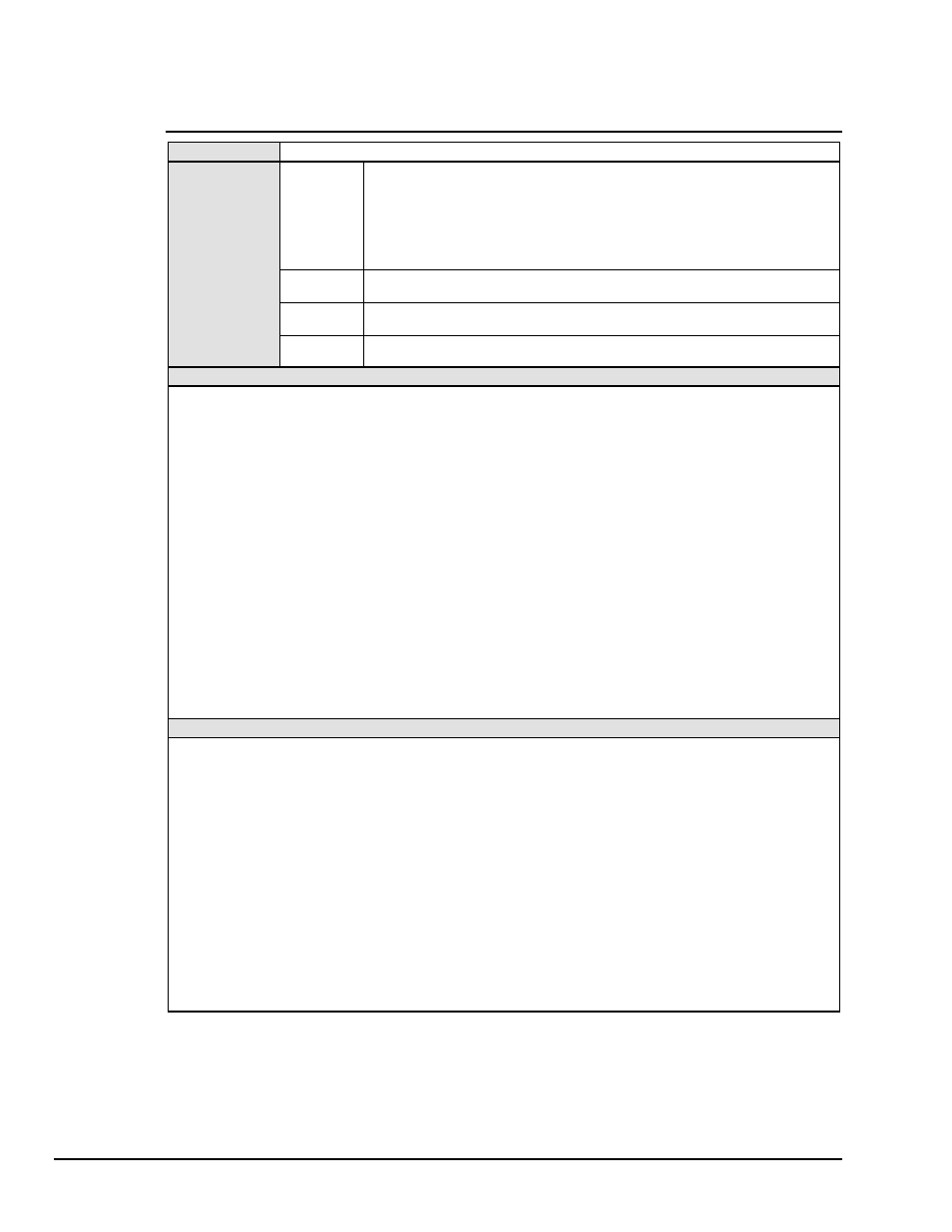
TYPE
Port Command
SYNTAX
Brng,
volts
Writes a voltage value in the buffer for the selected DAC port where
rng
selects
the range and is one of the following:
•
When rng = 0, then Range = Ground
•
When rng = 1, then Range =
±
1 volt
•
When rng = 2, then Range =
±
5 volt
•
When rng = 3, then Range =
±
10 volt
and where
volts
is any voltage value specified as a number without a V prefix.
Brng,
#bits
Writes voltage value in bits to the buffer for selected DAC port
Brng,
#$hexZ
Writes voltage value in hexadecimal bits to the buffer for selected DAC port.
Hexadecimal values must be followed by a
Z
.
B?
Returns the range and voltage value at the location pointer for the selected DAC
port in the format specified by the Output Format (
On
) command.
DESCRIPTION
The Buffer Data command is used to write a voltage value to the internal buffer. The buffer data is written to the
location pointed to by the location pointer. The Location Pointer can be set to any location in the buffer by using the
Buffer Location (Lval) command. The range (rng) and voltage value (volts) must be specified when using the Buffer
Data command.
When creating a buffer of voltage values, the buffer is first defined using the Buffer Definition (Fstart,size) command,
the location pointer is set to the first location in the newly defined buffer by using the Buffer Location (Lval) command,
and the Buffer Data command is then used to fill the buffer.
The Execute (X) command must be used after each Buffer Data command. The location pointer will automatically
increment after each Buffer Data command is executed. Buffer data may be written to locations outside of the defined
buffer area for the selected port if so desired.
Note:
(1) Each use of this command will cause the location counter to increment after the value has been written
to or read from the buffer. (2) Factory default buffer values are range 0, zero volts. (3) If the Buffer Data
command is used more than once within a command string, each Buffer command must be followed by the
Execute (X) command.
Note:
The DAC488 may be stopped while in the waveform mode by sending the Waveform Control (C3)
command. This will halt the DAC488 but rearm it for another trigger from the bus.
EXAMPLE
PRINT#1,"CLEAR09"
Line 1: Reset the DAC488
PRINT#1,"OUTPUT09;A0 C3 P1 F0,2
G1 N3 L0 I2000 X"
Line 2: Disables autorange, select waveform control mode,
select port 1, define a buffer with the first location=0 and the
number of locations=2, select trigger on GET, number of
cycles=3, set location pointer to 0 (first location in the defined
buffer), set time interval between points to 2 seconds.
PRINT#1,"OUTPUT09;B2,3 X B2,4 X"
Line 3: Sets buffer location 0 to 3 volts, sets buffer location 1 to 4
volts. Note: The location pointer will increment after the B2,3
command is executed.
PRINT#1,"OUTPUT09;L0X"
Line 4: Sets location pointer back to 0 (first location). This is
done so that when the DAC488 is triggered, it will start the
sequence with the value in location 0.
PRINT#1,"TRIGGER"
Line 5: Trigger the DAC488. The DAC488 will output 3 volts,
pause 2 seconds, output 4 volts, pause 2 seconds, then repeat
the sequence 3 times.