C - control mode, Ode…… 61 – Measurement Computing DAC488 v.1 User Manual
Page 67
DAC488 User’s Manual
DAC488 Commands 61
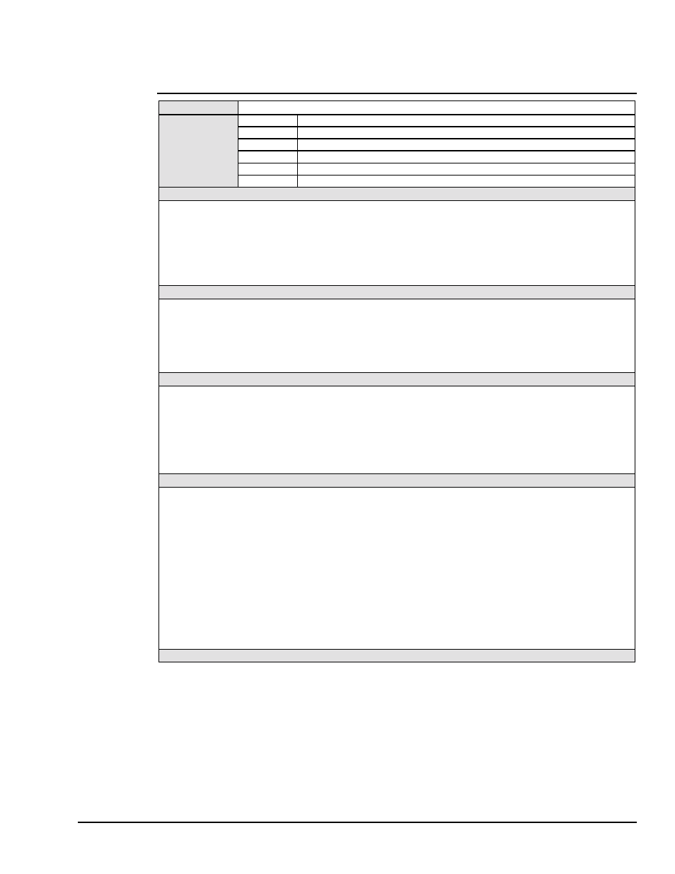
C - Control Mode
TYPE
Port Command
SYNTAX
Cn
Where
n = 0, 1, 2,
or
3
C0
(Default) Direct mode trigger on Execute (
X
) command.
C1
Indirect mode, trigger on
GET
, External trigger or
@
.
C2
Stepped mode, trigger on
GET
, External trigger or
@
.
C3
Waveform mode, trigger on
GET
, External trigger or
@
.
C?
Returns current control mode for selected port.
DESCRIPTION
The Control Mode command is used to select the operational mode of the DAC488. The modes and their operation
are described in the following four examples.
Note:
Issuing any control mode command stops the prior mode activity and rearms the port for the selected mode.
For example, if the DAC488 is generating a waveform, it may be halted and rearmed by issuing the C3
command.
EXAMPLE 1: Using the Direct Control mode.
PRINT#1,"CLEAR09"
Line 1: Reset the DAC488.
PRINT#1,"OUTPUT09;C0 P1
A0 R2 V4 X"
Line 2: Select Direct Control mode, select Port 1, disable autoranging, select
±
5 volt range, output 4 volts. The DAC488 will output 4 volts on Port 1 after
executing this command string.
EXAMPLE 2: Using the Indirect Control mode.
PRINT#1,"CLEAR09"
Line 1: Reset the DAC488.
PRINT#1,"OUTPUT09;C1 P1
T1 A0 R2 V4 X"
Line 2: Select Indirect Control mode, select Port 1, enable port 1 to trigger on
@, disable autoranging, select
±
5 volt range, output 4 volts.
PRINT#1,"OUTPUT09;@"
Line 3: The DAC488 will output 4 volts on Port 1 upon receiving the @
command.
EXAMPLE 3: Using the Stepped Control mode.
PRINT#1,"CLEAR09"
Line 1: Reset the DAC488.
PRINT#1,"OUTPUT09;C2 P1
F0,3 L0 Q1 X"
Line 2: C2 selects Stepped Control mode, P1 selects port 1, F0,3 defines a
buffer with the first location as location 0 and the number of values in the
sequence to 3, L0 sets the location pointer back to 0 (first location) and Q1
enables port 1 to trigger on an external trigger.
PRINT#1,"OUTPUT09;B1,1
X B2,3 X B2,4 X"
Line 3: B1,1X selects the
±
1 volt range, 1 volt for first point, B2,3X selects the
±
5 volt range, 3 volts for second point and B2,4X selects the
±
5 volt range,
4 volts for third point.
PRINT#1,"OUTPUT09;L0 X"
Line 4: L0 sets the location pointer is set back to location 0 before the port is
triggered. If this is not done, the location pointer will start at location 3, not
location 0. The output of the sequence is controlled by the rate at which
external triggers occur.
EXAMPLE 4: Using the Waveform Control mode. (See next page.)