Internal buffer, Buffer data, Buffer data…… 26 – Measurement Computing DAC488 v.1 User Manual
Page 32
26 DAC488 Operation
DAC488 User’s Manual
Internal Buffer
Buffer Data
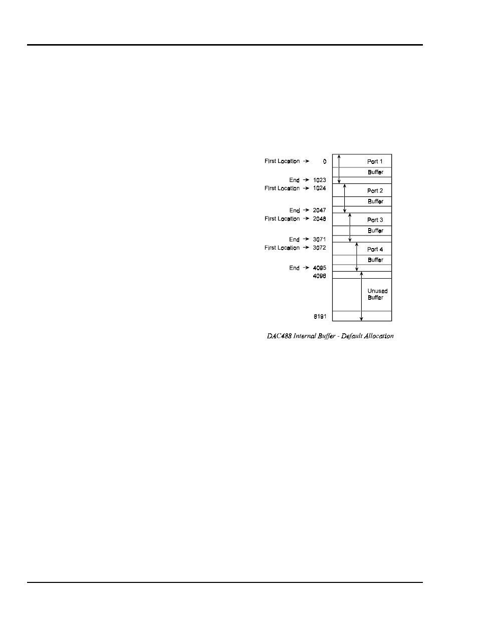
The DAC488 contains an internal buffer consisting of 8,192 locations numbered 0 to 8,191. The buffer is
shared by all ports. Each port may be given a different section of the buffer or ports may use the same
buffer locations without conflict.
This buffer may be loaded with voltage values to be output when the Stepped or Waveform modes are used.
All data in the internal buffer is saved in Non-Volatile RAM. Therefore buffer data which was previously
loaded will be available at power on. Examples showing the use of the internal buffer are given in the
upcoming descriptions of Stepped and Waveform Control modes.
The following diagram shows the factory
default allocation of the internal buffer to
each of the DAC ports on the DAC488/4. On
the DAC488/2, only the Port 1 and Port 2
sections of the internal buffer are allocated.
Buffers are defined using the Buffer
Definition (
F
) command. The parameters of
this command specify the starting location
(
start
) and the number of locations (
size
)
in the defined buffer. Once the buffer is
defined it may be loaded with voltage values
using the Buffer Data (
B
) command.
Before using the Buffer Data command, the
Buffer Location (
L
) command should be used
to set the location pointer to the desired
value. The location pointer points to the area
where data will be stored when the Buffer
Data command is used. After each use of the
Buffer Data command, the location pointer is
incremented.