Hoefer IEF100 User Manual
Page 34
• p28
6
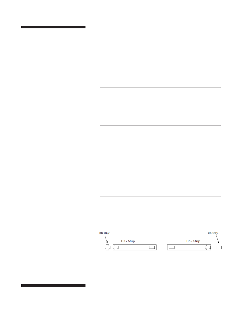
The second set of IPG strips are loaded to the right of the first set in the
opposite orientation — with the anodic end (+) of the strips matching the (–)
on the tray and the IEF100. The cathodic end (–) of the each set of strips
should be facing each other in the center of the focusing tray, approximately
4 cm apart (Fig. 29).
7
Parallel IPG strips should be aligned as closely as possible using the (+) or
(–) imprinted on the strip to guide alignment.
8
Apply electrode wicks on top of each end of the IPG strips, overlapping the
gel by 2–3 mm, and extending off the end of the IPG strip.
• The electrode wicks are supplied in long perforated strips. Use scissors to
cut off the desired number of wicks.
• Moisten the IEF wicks with water and gently blot off any excess water.
9
Connect the anode electrodes (+) to the positive (+) terminal on the left side
of the IEF100.
0
The anode electrodes are placed on either end of the focusing tray — the left
side of the first set of IPG strips and the right side of the second set of IPG
strips. The electrodes should be centered on top of the area where the wick
overlaps the gel of the IPG strip.
!
Connect the cathode electrodes (–) to the negative (–) terminal on the right
side of the IEF100.
@
The cathode electrodes are placed in the center of the focusing tray — on the
right side of the first set of IPG strips and the left side of the second set of
IPG strips. The electrodes should be centered on top of the area where the
wick overlaps the gel of the IPG strip.
Fig. 29. IPG Strip Placement.