Gasboy FuelOmat Payment Terminal User Manual
Page 23
OrPT Manual
13
2-5.1. Connectors Pin-Out Description
Use required mating connectors included in the OrPT kit according to the selected configuration.
The following connectors are located at the OrPT connector panel.
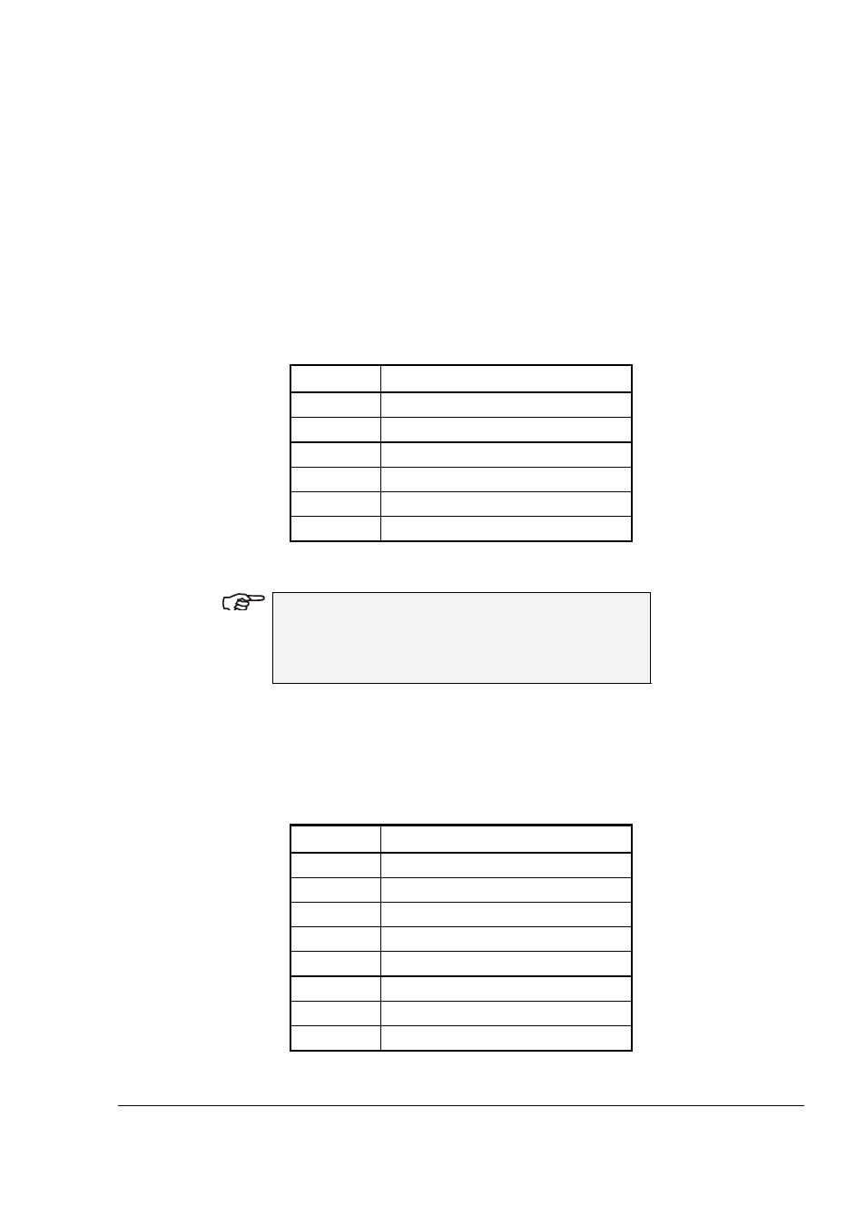
a. J2: Power
&
RS-485,
Connector
Type:
Phoenix
MC
1.5/6-GF-3.81
or
compatible
Function:
1.
RS-485
serial
communication
2.
15-24
Vdc
power
supply
to
the
unit.
Table 2-2. J2 - Power & RS-485 Connector
Pin No.
Functionality
1
VIN- (DC Power Supply GND)
2
VIN+ (DC PLUS Voltage)
3 SIGNAL
GND
(*)
4
EARTH (RS-485 Cable Shield)
5 RS-485
-Data
6 RS-485
+Data
(*) Connection to an external grounding.
N
N
O
O
T
T
E
E
To connect to RS-485 lines, use UL approved
Shielded Twisted Pair cable designated for RS-485
communication.
b. J3: LAN
Connector
Type:
RJ-45
8
pins
connector,
10
BASE
T
Function:
In Ethernet connectivity, routes TCP/IP comm. to/from
system controller.
Table 2-3. J3 – LAN Connector
Pin No.
Functionality
1 OUTPUT
+DATA
2 OUTPUT
-DATA
3 INPUT
+DATA
4 NOT
USED
5 NOT
USED
6 INPUT
-DATA
7 NOT
USED
8 NOT
USED